
Office storage box convenient to move

A technology for convenient movement and storage boxes, which is applied to the parts of bottles/cans, rigid containers, containers, etc., which can solve the problems of poor mobility of office storage boxes and achieve the effect of reducing bumps

Active Publication Date: 2020-05-19
北京世纪京美家具(淮北)有限责任公司
View PDF16 Cites 0 Cited by
  • Summary
  • Abstract
  • Description
  • Claims
  • Application Information

AI Technical Summary

Problems solved by technology

[0004] The purpose of the present invention is to solve the disadvantage of poor mobile convenience of office storage boxes in the prior art, and propose a convenient mobile office storage box

Method used


Image

  • Office storage box convenient to move
  • Office storage box convenient to move
  • Office storage box convenient to move

Examples


Embodiment 1

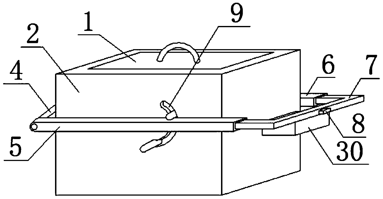
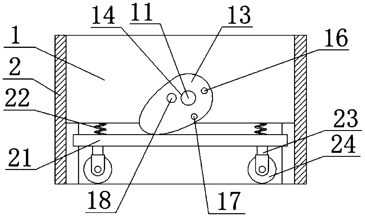
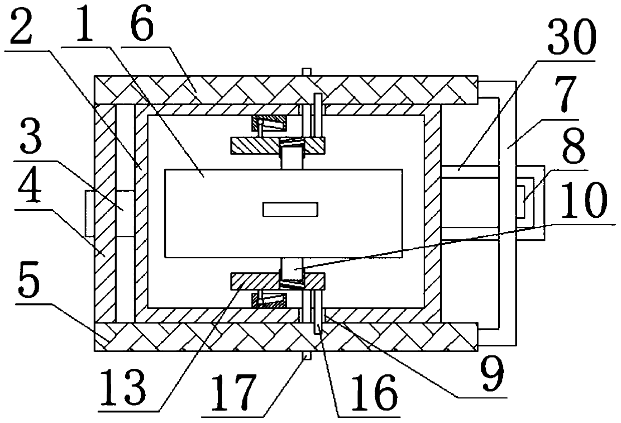
[0033] refer to Figure 1-9 , a convenient mobile office storage box, including a storage box body 1, the side of the storage box body 1 is fixedly provided with a shell 2, the shape of the shell 2 is irregular, so that the shell 2 and the storage box body 1 are partially connected Under normal circumstances, there is a gap between the shell 2 and the storage box body 1, and one side of the shell 2 is fixedly installed with a fixing base 3, and a third through hole is opened on the fixing base 3, and a cross bar 4 is fixedly installed in the third through hole. The first connecting rod 5 and the second connecting rod 6 are respectively rotated at both ends of the cross bar 4, and the first connecting rod 5 and the second connecting rod 6 are provided with a first chute and a second chute respectively. The chute and the second chute are jointly slidably installed with the same pull rod 7, and the side of the shell 2 away from the fixed seat 3 is fixedly equipped with a pull rin...

Embodiment 2

[0044] refer to Figure 1-9 , a convenient mobile office storage box, including a storage box body 1, the side of the storage box body 1 is fixedly provided with a shell 2, the shape of the shell 2 is irregular, so that the shell 2 and the storage box body 1 are partially connected Under normal circumstances, there is a gap between the shell 2 and the storage box body 1, and a fixed seat 3 is welded on one side of the shell 2, and a third through hole is opened on the fixed seat 3, and a cross bar 4 is welded in the third through hole, and the horizontal bar 4 is welded in the third through hole. The first connecting rod 5 and the second connecting rod 6 are respectively rotated at the two ends of the rod 4, and the first connecting rod 5 and the second connecting rod 6 are respectively provided with a first chute and a second chute, and the first chute The same pull rod 7 is installed jointly with the second chute, and the side of the shell 2 away from the fixed seat 3 is fix...


PUM


Abstract

The invention belongs to the technical field of office furniture, and particularly relates to an office storage box convenient to move. Aiming at solving the problem of poor moving convenience of an existing office storage box, the following scheme is put forward currently, specifically, the office storage box comprises a storage box body, the side face of the storage box body is provided with a shell in a sleeved mode, a fixing seat is mounted on one side of the shell, a third through hole is formed in the fixing seat, a cross rod is mounted in the third through hole, the two ends of the cross rod are rotationally provided with a first connecting rod and a second connecting rod correspondingly, a first sliding groove and a second sliding groove are formed in the first connecting rod and the second connecting rod correspondingly, and the first sliding groove and the second sliding groove are internally provided with the same pull rod jointly. According to the office storage box convenient to move, in order to facilitate movement of the storage box body, structures such as the pull rod and rollers are arranged for cooperation, meanwhile in order to enable the pull rod and the rollers to be able to cooperate more conveniently, structures such as cams are arranged, and up-down movement of the rollers driven by the pull rod through the structures such as the cams enable the rollersto stretch out if and only if the pull rod is pulled up.

Description

technical field [0001] The invention relates to the technical field of office furniture, in particular to a convenient mobile office storage box. Background technique [0002] The office storage box is a kind of storage box specially used for storing office supplies, which is different from ordinary storage boxes. It belongs to a kind of office furniture. Parts make the structure inside the box more convenient to classify and fix various office supplies. [0003] The utility model patent with the publication number CN208070374U discloses a convenient mobile office storage box. It includes a box body and a lifting handle. There are installation grooves on both sides of the box body. The end of the installation groove near the bottom of the box body is also provided with a The box body is also provided with a matching hole, which is located on the side of the installation groove close to the axis line of the box body. The lifting handle includes a handle, a base, a cover plat...

Claims


Application Information

Patent Timeline
IPC IPC(8): B65D25/10B65D25/20
CPCB65D25/103B65D25/20
Inventor 李健张玉飞汤建设
Owner 北京世纪京美家具(淮北)有限责任公司
Features
  • Generate Ideas
  • Intellectual Property
  • Life Sciences
  • Materials
  • Tech Scout
  • Unparalleled Data Quality
  • Higher Quality Content
  • 60% Fewer Hallucinations
Learn More