Laminated core and method for manufacturing the same

a technology of laminated cores and manufacturing methods, applied in the field of laminated cores, can solve the problems of reducing the efficiency and vibration of motors, adversely affecting the quality of motors, and the thickness of laminated cores, and achieve the effect of reducing the bulge of the connecting portion

Inactive Publication Date: 2010-12-07
MITSUI HIGH TEC INC
View PDF25 Cites 14 Cited by
  • Summary
  • Abstract
  • Description
  • Claims
  • Application Information

AI Technical Summary

Benefits of technology

[0009]Accordingly, the formation of gaps between the laminated segment core sheets is inhibited, and further prevented. Thus, the quality control of the laminated core becomes easy, and the vibration of motors using the laminated cores is prevented to improve the efficiency of the motors.
[0026]In such a case, a compressive stress in the vicinity of the center of curvature of the connecting portion caused by bending the connecting portion is decreased, which inhibits a force of the connecting portion to expand in the thickness direction and thus reduces the bulge of the connecting portion.

Problems solved by technology

The bulges create gaps between the laminated segment core sheets, thereby causing variations in thicknesses of manufactured laminated cores.
Furthermore, the gaps cause reduced efficiency and vibration in the motors, thereby adversely affecting the quality of the motors.

Method used


Image

  • Laminated core and method for manufacturing the same
  • Laminated core and method for manufacturing the same
  • Laminated core and method for manufacturing the same

Examples


Embodiment Construction

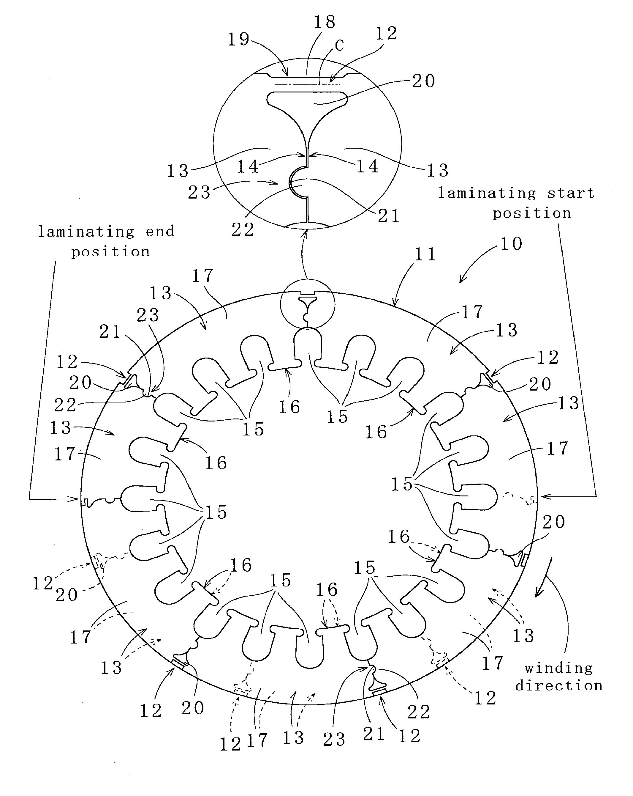
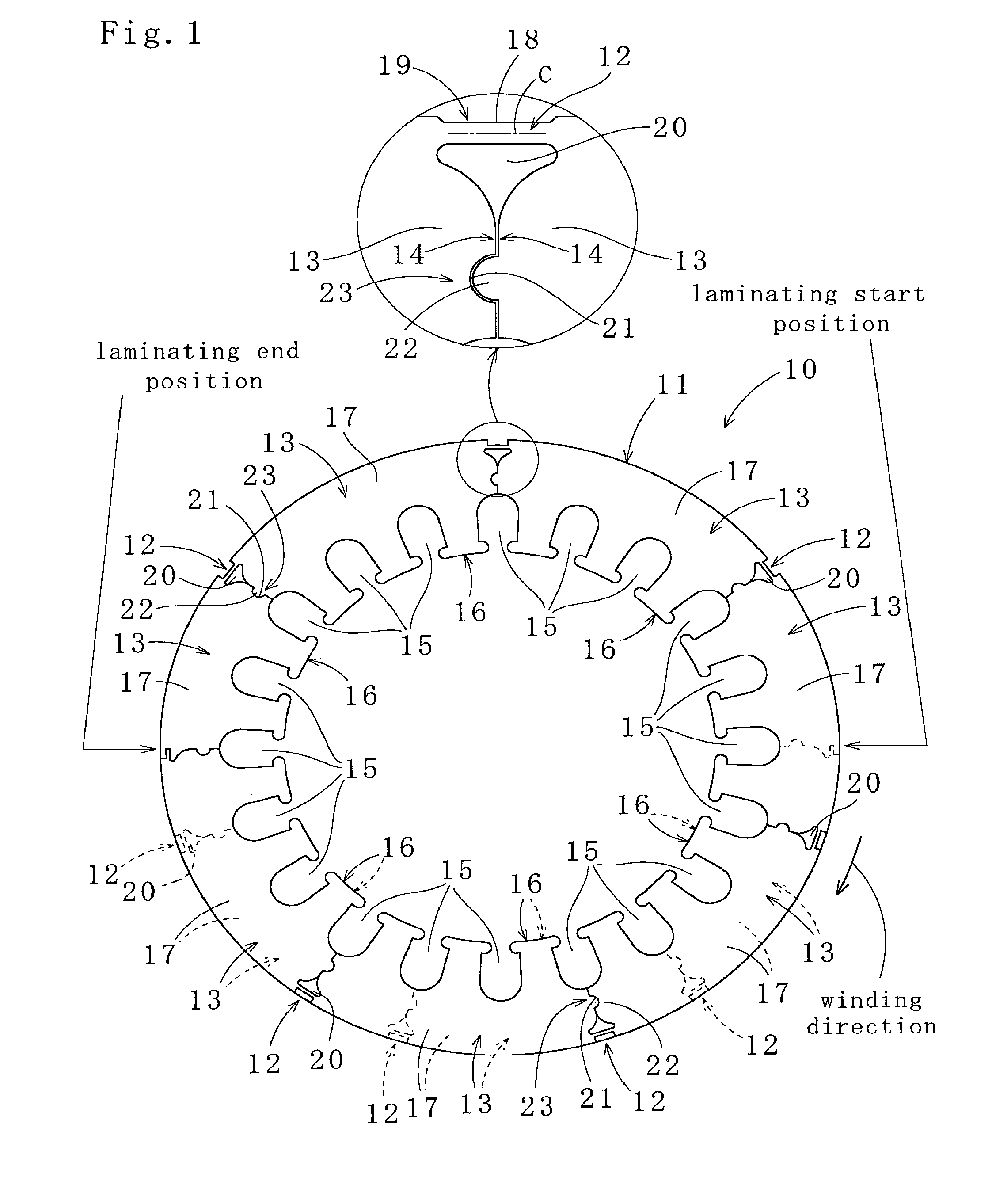
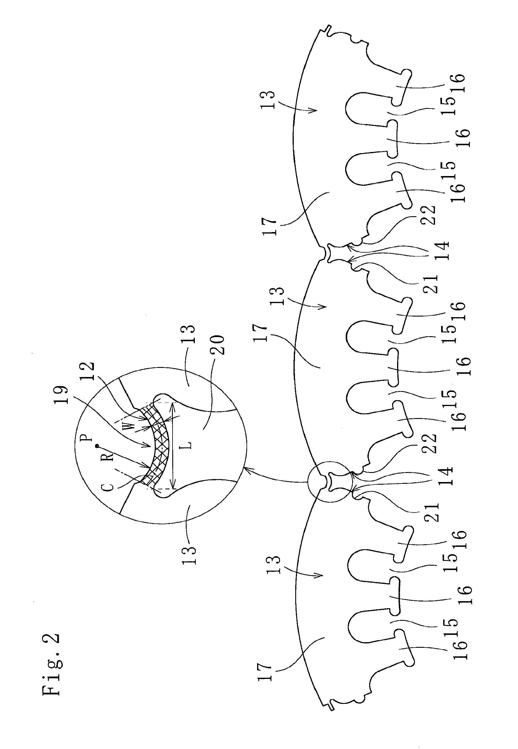
[0033]As illustrated in FIGS. 1 and 2, a laminated core 10 according to one embodiment of the present invention is a laminated stator core (also referred to as a stator). The laminated core 10 includes segment core sheets 13 continuous with one another by connecting portions 12 located in an outer peripheral portion 11. The connecting portions 12 are wound in a spiral form and laminated while the connecting portions 12 are bent and side edges 14 of the segment core sheets 13 are fitted with each other. A width W in the radial direction of the connecting portion 12 before being bent is narrow. The above components are described in detail hereunder.

[0034]The plurality of segment core sheets 13 coupled by the connecting portions 12 are punched out using dies from a magnetic steel sheet (not illustrated) having a thickness of, e.g., less than or equal to about 0.5 mm (0.35 mm in this embodiment). As illustrated in FIGS. 1 and 2, the segment core sheets 13 in series are wound, laminated,...


PUM

PropertyMeasurementUnit
thicknessaaaaaaaaaa
thicknessaaaaaaaaaa
elongationaaaaaaaaaa

Abstract

A laminated core (10) and a method for manufacturing the same, the laminated core (10) formed with a plurality of continuous segment core sheets (13) wound and laminated in a spiral form while connecting portions (12) mutually connecting the adjacent segment core sheets (13) are bent and side edges of the adjacent segment core sheets (13) are fitted with each other, the connecting portions (12) being located in an outer peripheral portion (11) of the laminated core (10), the laminated core (10) comprising:a concave cutout (19) provided at a radially outward side of the connecting portion (12), the concave cutout (19) allowing a radial bulge (18) to be accommodated within an outer circle of the laminated core (19), the radial bulge (18) formed at a radially outward side of the connecting portion (12) by bending the connecting portion (12); andan inward cutout (20) provided at a radially inward side of the connecting portion (12), the inward cutout (20) defining a bending position of the connecting portion (12), wherein the connecting portion (12) has a narrow radial width and, before being bent, has a radial width in the range of 0.5 to 5 times a thickness of the segment core sheet (13).The laminated core (10) and the method for manufacturing the same are capable of producing a highly-efficient and high-quality product that is free from effects of the swell in the thickness direction of the connecting portion (12).

Description

TECHNICAL FIELD[0001]The present invention relates to a laminated core formed by spirally winding and laminating a plurality of segment core sheets continuous with one another in a band shape, and to a method for manufacturing the laminated core.BACKGROUND ART[0002]For improving yield of core materials (e.g., strip materials) used for producing laminated cores, there has been known so-called wound cores produced by punching out from a core material not a plurality of continuous segment core sheets in a ring shape but a plurality of segment core sheets in a band shape and winding and laminating the segment core sheets.[0003]In particular, arc-shaped segment core sheets connected together by connecting portions and having a predetermined number of slots are punched out from a core material using dies. Then, the continuous segment core sheets are wound in a spiral form and laminated while the connecting portions located in outer peripheral portions of the segment core sheets are bent a...

Claims


Application Information

Patent Timeline
Patent Type & Authority Patents(United States)
IPC IPC(8): H02K1/06
CPCH02K1/148Y10T29/49009
Inventor NAGAI, AKIRAMYOJIN, IWAO
Owner MITSUI HIGH TEC INC
Why Eureka
Try Eureka