
Device for connecting lifting mechanism and working box and applied to 3D printer

A 3D printer and lifting mechanism technology, applied in the field of additive manufacturing, can solve the problems of inability to keep the level descending or descending slowly, unable to reach the expected position quickly and smoothly, and the molding accuracy is not up to standard, so as to overcome the influence of friction and have a simple structure. , refit or create convenient effects

Pending Publication Date: 2020-05-19
KOCEL INTELLIGENT FOUNDRY IND INNOVATION CENT CO LTD
View PDF7 Cites 1 Cited by
  • Summary
  • Abstract
  • Description
  • Claims
  • Application Information

AI Technical Summary

Problems solved by technology

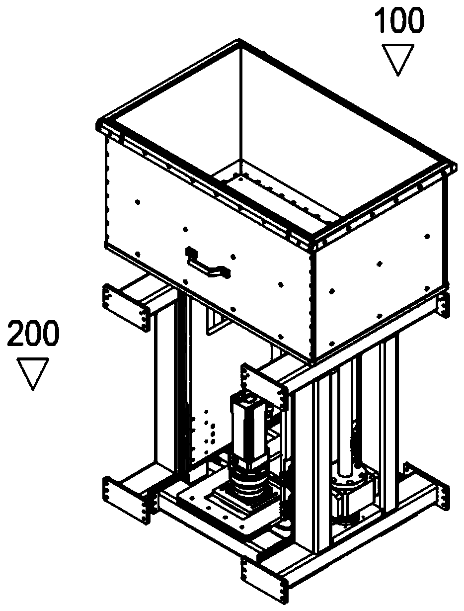
[0003] Aiming at the problem that the bottom plate of the 3D printer work box is light, the level cannot be maintained or the descent is slow during the descent process, and the expected position cannot be reached quickly and stably, resulting in the substandard forming accuracy, and a lifting mechanism applied to the 3D printer is provided. The connection device with the working box, in the non-printing process, the working box is separated from the lifting mechanism, which is convenient for maintenance; in the printing process, the working box is connected with the lifting mechanism, so that the bottom plate of the working box can follow the lifting mechanism horizontally, smoothly and quickly The lifting mechanism reaches the expected position, which improves the printing accuracy of the equipment

Method used


Image

  • Device for connecting lifting mechanism and working box and applied to 3D printer
  • Device for connecting lifting mechanism and working box and applied to 3D printer
  • Device for connecting lifting mechanism and working box and applied to 3D printer

Examples


Embodiment Construction

[0015] In order to facilitate the understanding of the present invention, the present invention will be described more fully below with reference to the associated drawings. Preferred embodiments of the invention are shown in the accompanying drawings. However, the present invention can be embodied in many different forms and is not limited to the embodiments described herein. On the contrary, the purpose of providing these embodiments is to make the disclosure of the present invention more thorough and comprehensive.

[0016] It should be noted that when an element is referred to as being “disposed on” another element, it may be directly on the other element or there may also be an intervening element. When an element is referred to as being "connected to" another element, it can be directly connected to the other element or intervening elements may also be present. The terms "vertical", "horizontal", "left", "right", "top", "bottom", "bottom", "top" and similar expressions...


PUM


Abstract

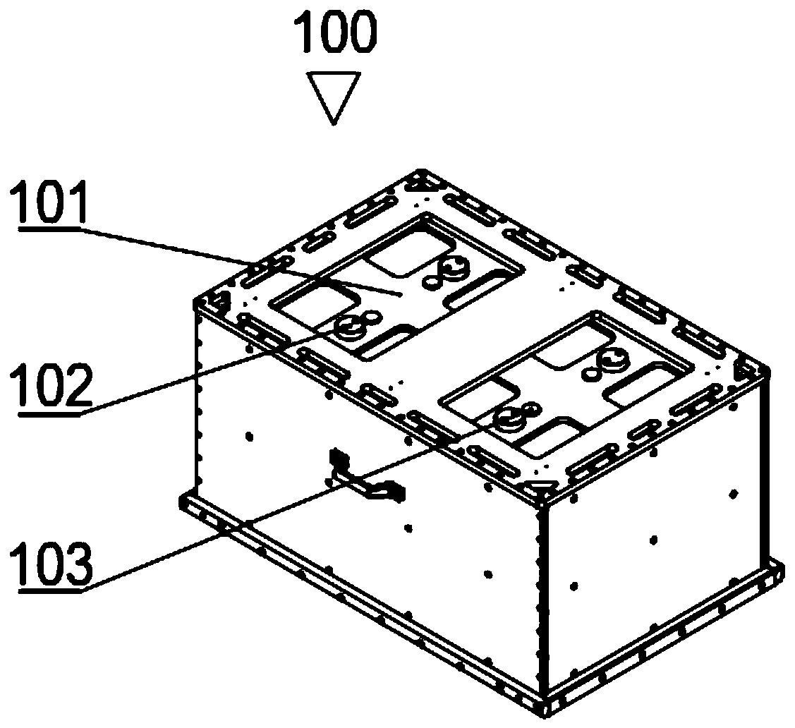
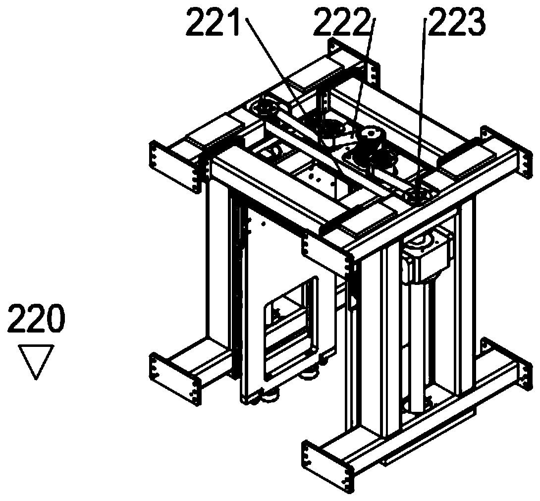
The invention relates to a device for connecting a lifting mechanism and a working box and applied to a 3D printer. The device comprises the working box, the lifting mechanism and an even number of electric suction discs, the electric suction discs are arranged at the top of the lifting mechanism and connect the working box with the lifting mechanism through magnetic force, and the electric suction discs are symmetrically arranged at the top of the lifting mechanism; and the lifting mechanism comprises a main frame, a driving member and lifting members, the driving member is arranged inside the main frame, and the lifting members are symmetrically arranged on both sides of the main frame correspondingly. According to the device for connecting the lifting mechanism and the working box and applied to the 3D printer, the fact that an existing working box can't keep the horizontal descent or descends too slowly , and can't reach the expected position quickly and stably in the descent process is overcome, in the non-printing process, the working box is separated from the lifting mechanism, and the maintenance is facilitated; and in the printing process, the working box is connected withthe lifting mechanism through the electric suction discs, a bottom plate of the working box can reach the expected position horizontally, stably and quickly, and the device printing accuracy is improved.

Description

technical field [0001] The invention relates to the technical field of additive manufacturing, in particular to a connection device applied to a lifting mechanism of a 3D printer and a working box. Background technique [0002] A 3D printer lifting mechanism structure is disclosed in the patent "A Lifting Mechanism Applied to 3D Printing Workbox" (application number CN201620759441.4, publication number CN205851790U). This structure is mainly to separate the working box and the lifting mechanism in 3D printing. It is not an integral structure. The servo motor is used to drive the screw to rotate, and then drive the screw nut to lift. The screw nut is connected to the lifting top plate to lift The top plate uses the lifting block to drive the bottom plate of the working box to carry out lifting movement. When this patent is actually used, it is found that when the mass of the bottom plate of the working box in the 3D printing equipment is small, due to the friction between th...

Claims


Application Information

Patent Timeline
Patent Type & Authority Applications(China)
IPC IPC(8): B66F7/14B29C64/30B33Y40/00
CPCB66F7/14B33Y40/00
Inventor 王冕周志军王浩彭凡
Owner KOCEL INTELLIGENT FOUNDRY IND INNOVATION CENT CO LTD
Learn More