Jacking mechanism

A jacking mechanism and jacking technology, applied in the direction of lifting devices, etc., can solve the problems of affecting the jacking accuracy, complex equipment structure, high failure rate, etc., and achieve the effect of guaranteed service life, flexible selection, and high jacking accuracy

Active Publication Date: 2014-09-17
API ZC PRECISION INSTUMENT CO LTD
View PDF6 Cites 1 Cited by
  • Summary
  • Abstract
  • Description
  • Claims
  • Application Information

AI Technical Summary

Problems solved by technology

[0004] In order to solve the problems of high failure rate, complicated equipment structure, inconvenient installation or affecting jacking accuracy in the above-mentioned prior art, the present invention provides a jacking mechanism

Method used


Image

  • Jacking mechanism
  • Jacking mechanism
  • Jacking mechanism

Examples


Embodiment 1

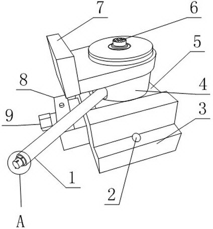
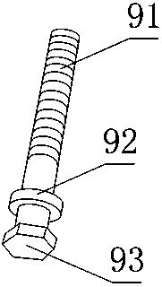
[0031] Such as Figure 1 to Figure 6 , a jacking mechanism provided by the present invention includes a base 3, a traverse part that can move laterally along the base 3, and a lifting part arranged on the traverse part, and the traverse part includes a traverse seat 5 and a traverse handle 9. The base 3 is provided with a rotating seat 8, and the rotating seat 8 is provided with a ring convex cavity 83, and the traverse handle 9 includes a braking part 93, an annular protrusion 92 and a threaded section sequentially from one end to the other end thereof 91, the annular protrusion 92 is located in the ring convex cavity 83, the lower end of the traversing seat 5 is in contact with the upper end of the base 3, and the traversing seat 5 and the traversing handle 9 are threadedly connected;

[0032] The lifting part includes a cylindrical internal thread seat 4, a lifting handle 1 and a jacking rod 6, the internal thread seat 4 is provided with an internal thread hole along its ax...

Embodiment 2

[0035] This embodiment is further limited on the basis of embodiment 1: as Figure 1 to Figure 6, in order to facilitate the installation of the traversing handle 9 and simplify the structure of the present invention, which is beneficial to processing, manufacturing and assembly, the rotating seat 8 includes an upper cover 82 and a lower cover 81 connected by bolts, and the upper cover 82 and the lower cover 81 Grooves are provided on the connecting sides, and the two grooves constitute the ring convex cavity 83 .

Embodiment 3

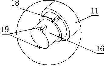
[0037] The present embodiment is further limited on the basis of embodiment 1: as Figure 1 to Figure 6 , the lifting handle 1 includes a driving sleeve 11 and a brake lever 16 sleeved in the driving sleeve 11, one end of the driving sleeve 11 is hingedly connected with the jacking rod 6, and the driving sleeve 11 can go around the top When the lifting rod 6 rotates in the circumferential direction, one end of the brake rod 16 that penetrates into the drive sleeve 11 forms an oblique cutout 7 , and the other end of the brake rod 16 protrudes relative to the drive sleeve 11 .

[0038] The set driving sleeve 11 is convenient for fixing the relative position of the lifting handle 1 relative to the jacking rod 6: even if the brake rod 16 interacting with the axial teeth 41 is always located in the radial direction of the jacking rod 6, the set inclined The notch 17 makes the structural relationship between the lifting handle 1 and the axial tooth 41 a ratchet structure. By adjusti...


PUM


Abstract

The invention discloses a jacking mechanism which comprises a base, a transverse movement part and a lifting part, wherein the transverse movement part comprises a transverse movement base and a transverse movement handle; the base is provided with a rotary seat which is internally provided with a ring convex cavity; the transverse movement handle comprises a braking part, a ring-shaped bulge and a thread section; the ring-shaped bulge is arranged in the ring convex cavity; the transverse movement base is connected with the transverse movement handle by screw threads; the lifting part comprises an internal thread seat, a lifting handle and a jacking rod; an internal thread hole is formed in the internal thread seat; the jacking rod is provided with external threads and a plurality of axial teeth; the length directions of the axial teeth are parallel to the axis of the jacking rod; the external threads arranged on the jacking rod are connected with the internal thread hole by screw threads; the internal thread seat is fixedly connected with the transverse movement base; the transverse movement handle is vertical to the jacking rod; a sealing ring is also arranged between the upper end of the jacking rod and the internal thread seat. The jacking mechanism is flexible in selection of a support point and can be conveniently installed relatively to a device to be jacked; furthermore, the jacking mechanism is long in service life, high in bearing capacity and high in jacking accuracy.

Description

technical field [0001] The invention relates to a device for supporting or leveling heavy objects, in particular to a jacking mechanism. Background technique [0002] Jacking equipment is mainly used in the hoisting, assembly, maintenance and installation of large-scale equipment and components to achieve leveling of equipment or components in the above process, and to create a gap between the bottom plate of the equipment and the ground to facilitate the positioning of the fork of the forklift or in the equipment. A rolling body is set between the ground and the ground. [0003] In the prior art, the above lifting equipment mostly adopts mechanical jacks, hydraulic jacks or hydraulic pump stations. However, in the prior art, it is more troublesome for the mechanical jacks and hydraulic jacks to realize their respective axial directions in the vertical direction, and the exposed threads of the mechanical jacks After dust is attached to it, it is easy to cause thread damage ...

Claims


Application Information

Patent Timeline
Patent Type & Authority Applications(China)
IPC IPC(8): B66F3/08
Inventor 刘宁罗成
Owner API ZC PRECISION INSTUMENT CO LTD
Why Eureka
Try Eureka