Shift register circuit and gate driving circuit

a technology of shift register and gate driving circuit, which is applied in the field of display technology, can solve the problems of lack of application flexibility and achieve the effect of improving the flexibility of the application of the gate driving circui

Active Publication Date: 2011-09-22
AU OPTRONICS CORP
View PDF19 Cites 33 Cited by
  • Summary
  • Abstract
  • Description
  • Claims
  • Application Information

AI Technical Summary

Benefits of technology

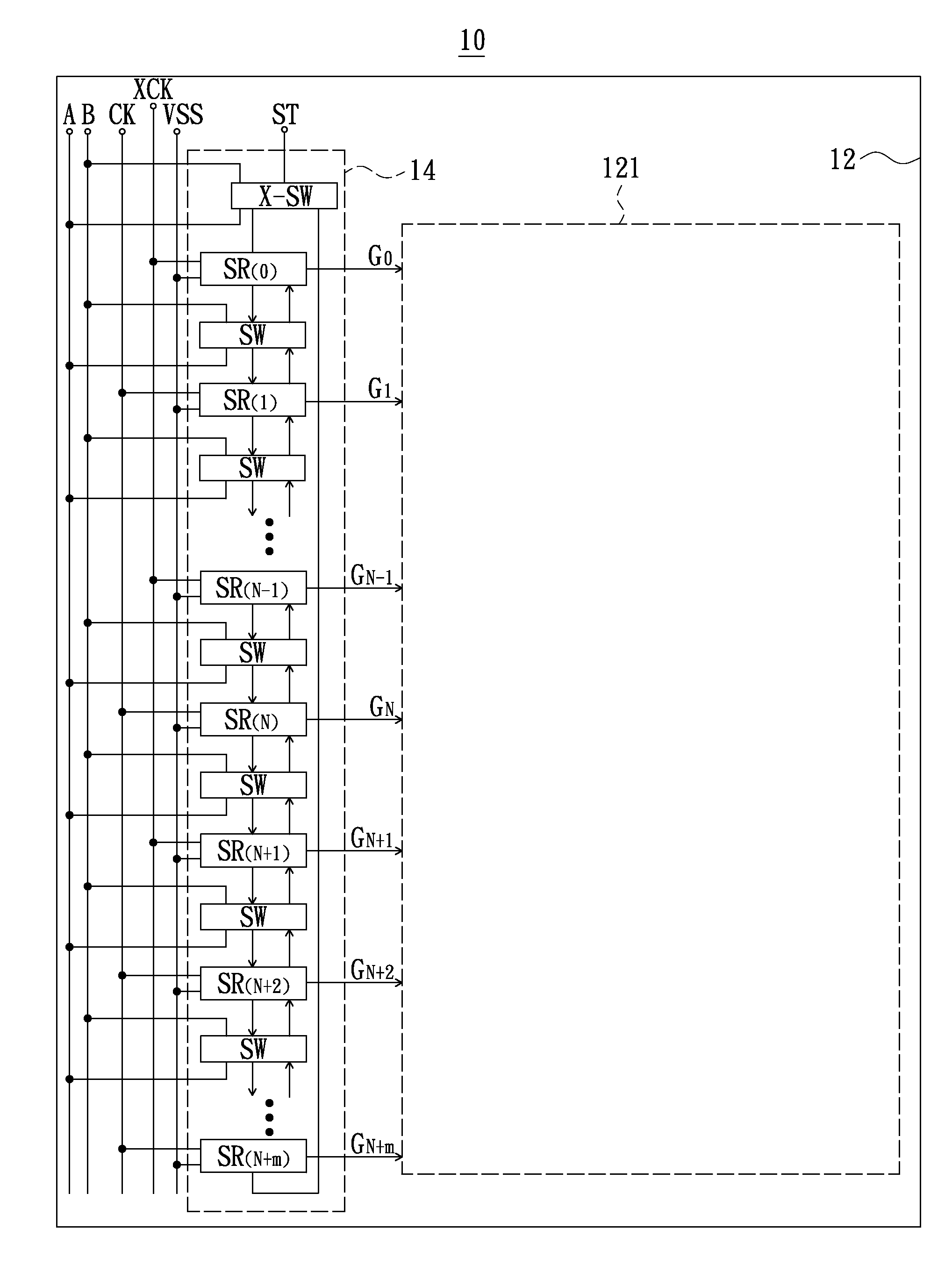
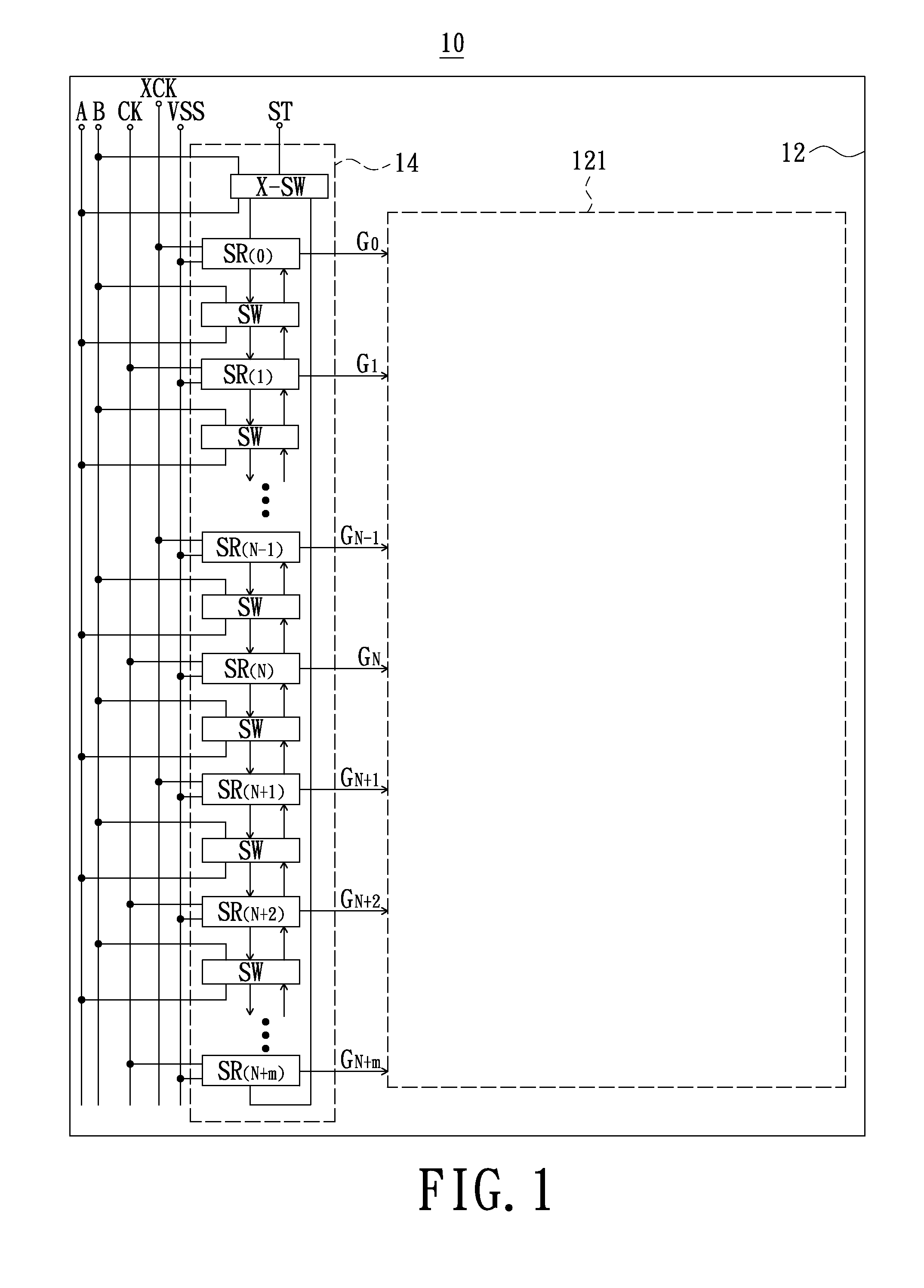
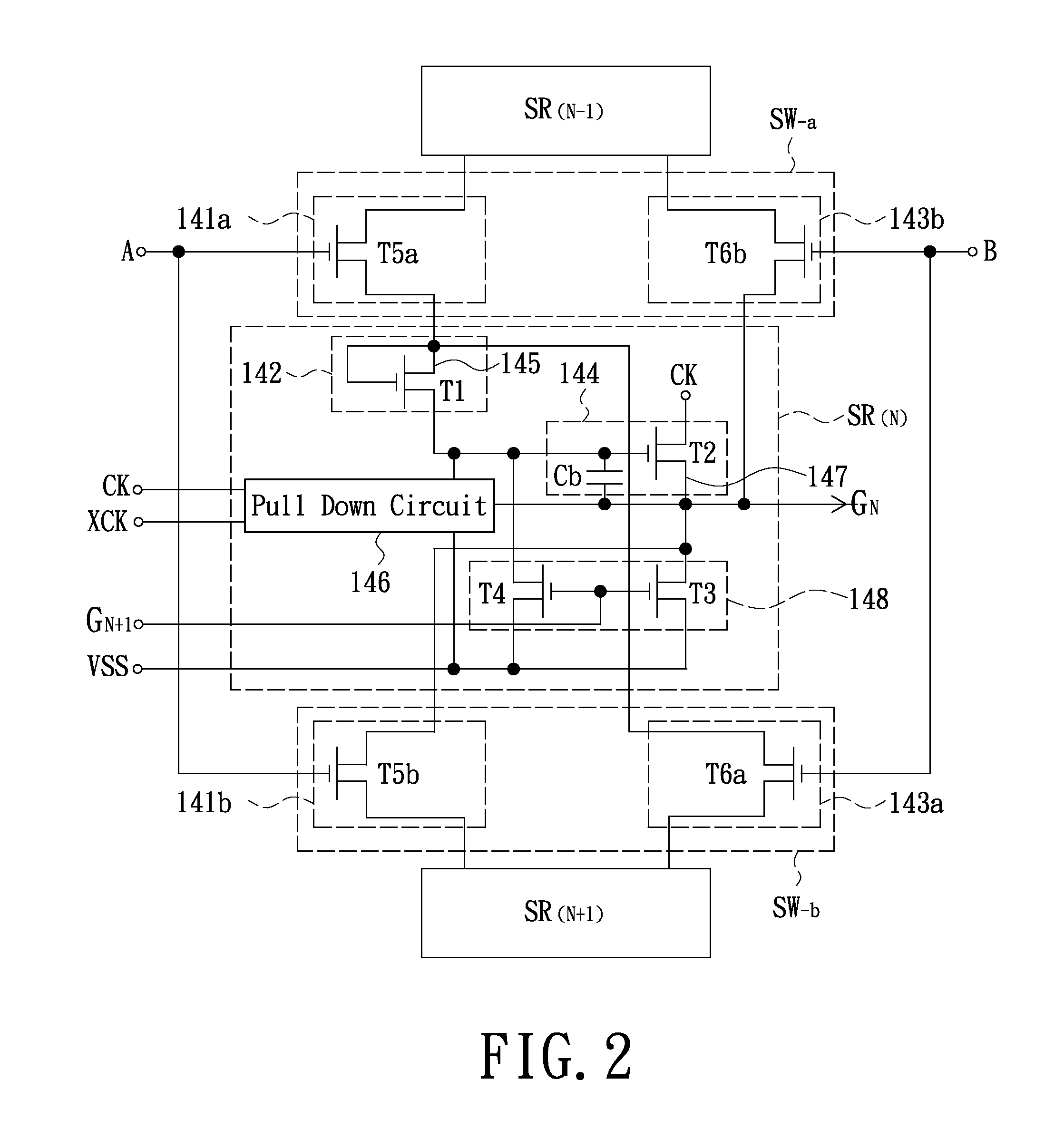
[0020]In summary, the above-mentioned embodiments of the present invention employs added switching circuits to determine the input/output path of start pulse signal in the shift register circuit, so that the transmission direction of the start pulse

Problems solved by technology

However, the GOA type gate driving circuit associated with the prior art only can perform single-direction scanning

Method used


Image

  • Shift register circuit and gate driving circuit
  • Shift register circuit and gate driving circuit
  • Shift register circuit and gate driving circuit

Examples


Embodiment Construction

[0026]In the following detailed description of the preferred embodiments, reference is made to the accompanying drawings which form a part hereof, and in which are shown by way of illustration specific embodiments in which the invention may be practiced. In this regard, the drawings are only schematic and the sizes of components may be exaggerated for clarity. It is to be understood that other embodiments may be utilized and structural changes may be made without departing from the scope of the present invention. Also, it is to be understood that the phraseology and terminology used herein are for the purpose of description and should not be regarded as limiting. The use of “including,”“comprising,” or “having” and variations thereof herein is meant to encompass the items listed thereafter and equivalents thereof as well as additional items. Unless limited otherwise, the terms “connected,” and “coupled” and variations thereof herein are used broadly and encompass direct and indirect...


PUM


Abstract

An exemplary shift register circuit includes a shift register, a first switching circuit and a second switching circuit. The shift register has a start pulse signal input terminal and a start pulse signal output terminal. The first switching circuit includes a first input switch unit and a second output switch unit respectively electrically coupled to the start pulse signal input terminal and the start pulse signal output terminal. The second switching circuit includes a second input switch unit and a first output switch unit respectively electrically coupled to the start pulse signal input terminal and the start pulse signal output terminal. Moreover, on-off states of the first input and first output switch units are opposite to on-off states of the second input and second output switch units. Moreover, a gate driving circuit using the above-mentioned shift register and switching circuits also is provided.

Description

BACKGROUND[0001]1. Technical Field[0002]The present invention generally relates to display technology fields and, particularly to a shift register circuit and a gate driving circuit.[0003]2. Description of the Related Art[0004]Nowadays, flat display devices such as liquid crystal displays have many advantages of high display quality, small volume, lightweight and wide application range and thus are widely used in consumer electronics products such as mobile phones, laptop computers, desktop computers and televisions, etc. Moreover, the liquid crystal displays have evolved into a mainstream display in place of cathode ray tube (CRT) displays.[0005]In order to make the display products to be more slim and more competitive at the aspect of cost, a gate driver on array (GOA) type gate driving circuit is proposed in the prior art to generate gate pulse signals. The GOA type gate driving circuit generally includes a plurality of cascade-connected shift registers directly fabricated on the...

Claims


Application Information

Patent Timeline
IPC IPC(8): G11C19/28
CPCG09G3/3674G11C19/28G09G2310/0286G09G2310/0283
Inventor WANG, PO-KAIHUANG, CHUN-HAOPENG, CHUNG-HUNG
Owner AU OPTRONICS CORP
Why Eureka
Try Eureka