
Intelligent wire releasing device for steel cable stranding

A wire feeding device and steel cable technology, which is applied in the field of bridge construction manufacturing, can solve problems such as unsynchronized wire feeding speed, inability to guarantee employee safety, accidental injury to employees, etc.

Pending Publication Date: 2020-05-19
CHONGQING LIYANG ELECTRICAL & MECHANICAL EQUIP MFG CO LTD
View PDF0 Cites 0 Cited by
  • Summary
  • Abstract
  • Description
  • Claims
  • Application Information

AI Technical Summary

Problems solved by technology

In order to ensure the construction period, such a large number of production tasks must be completed in a very short period of time, and the equipment in the production workshop must be increased. The more discs, the harder it is to control
At present, in the production process of steel wire and cable, the wire reel has no power and relies solely on the power of the traction equipment. The control of the wire reel is mainly controlled manually, and manual intervention is required from time to time.
In such a production mode, the production efficiency is limited, the pulling speed of the steel wire cannot be synchronized with the wire feeding speed of the wire reel, and the wire feeding speed of each wire reel will also have a large difference, and the tension of the steel wire cannot be controlled. It will have a certain impact on the quality of the finished cable, and it is also prone to jamming and wire skipping. However, the steel wire itself is elastic, and some wire reels are stuck and skipping wires, which can easily cause the steel wire to entangle with other equipment and even cause accidents to employees. Injury, the safety of employees cannot be guaranteed

Method used


Image

  • Intelligent wire releasing device for steel cable stranding
  • Intelligent wire releasing device for steel cable stranding
  • Intelligent wire releasing device for steel cable stranding

Examples


Embodiment Construction

[0021] An embodiment of the steel cable stranding intelligent wire feeding device of the present invention:

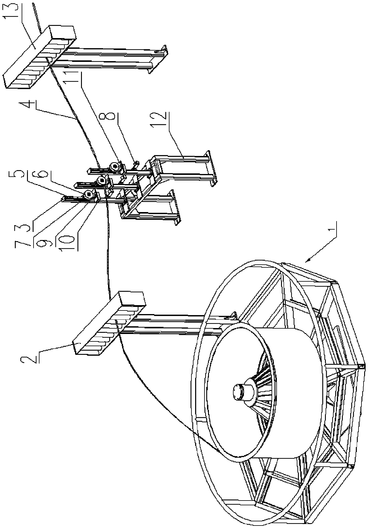
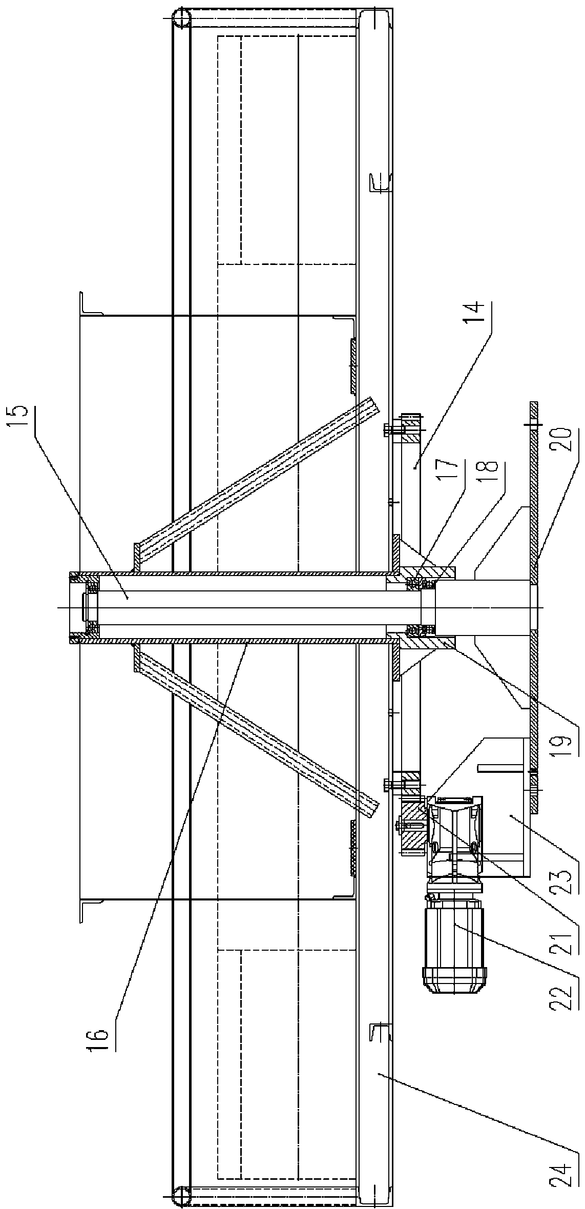
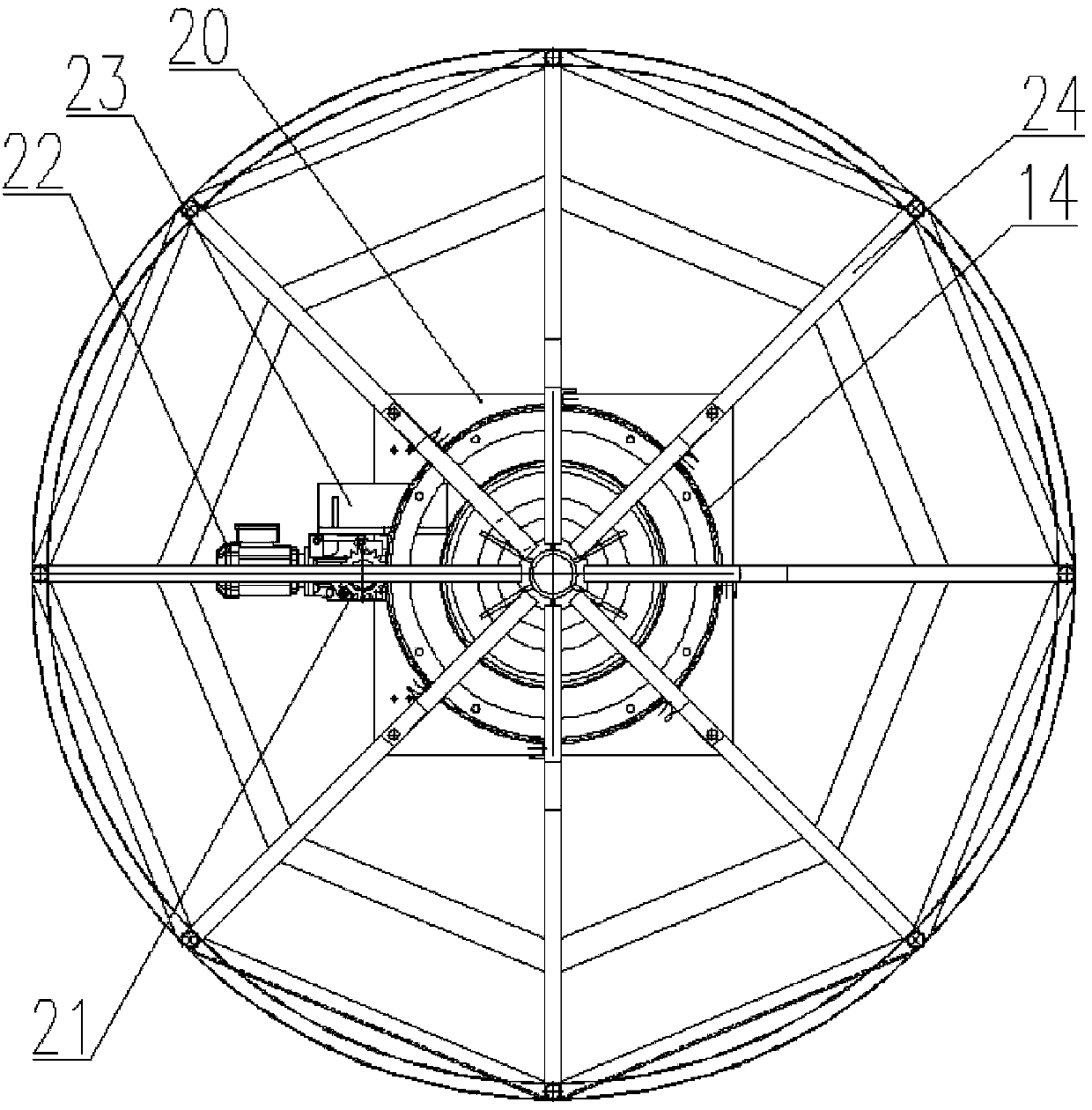
[0022] see Figure 1-Figure 3 , a steel cable stranding intelligent wire-releasing device, including a plurality of wire-releasing reels and wire management frames, each of which includes a base 20, a rotating frame 24, a reduction motor 22 controlled by a frequency converter, and a driving gear 21. The reduction driven gear 14, the base 20 is provided with an upright central shaft 15, the center of the rotating frame 24 is provided with a hollow column 16, and the lower end of the hollow column 16 is fixedly connected with a bearing seat 19, the The bearing seat 19 is slidingly matched with the central shaft 15 through the rolling bearing 17, the thrust bearing 18, the thrust bearing 18 is positioned by the shoulder of the central shaft 15, the thrust bearing 18 is used to support the axial load, and the rolling bearing 17 enables the bearing seat 19 to rotate , the ...


PUM


Abstract

The invention discloses an intelligent wire releasing device for steel cable stranding. The device comprises a plurality of wire releasing discs and cable management racks, wherein each wire releasingdisc comprises a base, a rotating frame, a gear motor controlled by a frequency converter, a driving gear and a speed reducing driven gear, a central shaft is arranged on the base, a hollow column isarranged at the center of the rotating frame, the hollow column is in sliding fit with the central shaft through a bearing, the speed reducing driven gear is arranged at the lower part of the rotating frame, and the driving gear engaged with the speed reducing driven gear is arranged on an output shaft of the gear motor; the cable management racks comprise a first cable management rack and a second cable management rack, wherein a floating roller measuring device is arranged between the first cable management rack and the second cable management rack; the floating roller measuring device comprises a mounting rack, floating rollers, displacement sensors and linear sliding rails, wherein a plurality of mounting columns are arranged on the mounting rack; one linear sliding rail is arranged on each mounting column; a sliding block is in sliding fit with the linear sliding rail; each floating roller is arranged on the corresponding sliding block; a balancing weight and a floating distancedetection board are arranged on each sliding block; one displacement sensor is arranged on each mounting column; and the frequency converters, the displacement sensors and a controller are electrically connected.

Description

technical field [0001] The invention relates to the field of bridge construction manufacturing, in particular to an intelligent wire feeding device for stranding steel cables. Background technique [0002] Steel wire cables are an important part of bridges such as cable-stayed bridges and suspension bridges and some building structures. They are load-bearing components and have a direct and important impact on the structural safety and service life of bridges and buildings. With the current development of bridges and buildings, the specifications of cables are also getting larger and larger, and there are large-scale, super-length, high-strength stay cables and suspension cables. Now cables have been widely used in bridges and buildings, and often a project requires dozens or even thousands of unit strands, and each unit strand is composed of hundreds of steel wires. In order to ensure the construction period, such a large number of production tasks must be completed in a v...

Claims


Application Information

Patent Timeline
Patent Type & Authority Applications(China)
IPC IPC(8): D07B7/02B21C47/28B21C51/00
CPCB21C47/28B21C51/00D07B7/02D07B2301/3583D07B2301/5586
Inventor 仝德云黄爽谭凌霄应征
Owner CHONGQING LIYANG ELECTRICAL & MECHANICAL EQUIP MFG CO LTD
Learn More