Modular self-balancing type inerter damper

A self-balancing, damper technology, applied in the direction of protective buildings/shelters, building components, building structures, etc., can solve the problem that the cable cannot provide braking torque, the plate-type and pendulum-type dampers do not meet the requirements, Unable to use pure tension system and other problems, to achieve the effect of simple and easy adjustment of damping coefficient, complete separation of damping and stiffness, and no need for lubrication

Pending Publication Date: 2020-05-19
TONGJI UNIV
View PDF0 Cites 1 Cited by
  • Summary
  • Abstract
  • Description
  • Claims
  • Application Information

AI Technical Summary

Problems solved by technology

The pure tension system of the central energy-dissipating member is a better damper installation method to meet the needs of rapid seismic reinforcement. If the eddy current damper can be introduced into the system for use, the easy installation performance of the eddy current damper will be better utilized. However, since the cable can only provide tension to the central energy-dissipating member and cannot limit the rotation, performance requirements such as light weight and self-balancing are put forward for the eddy current damper. Obviously, the plate-type and pendulum-type dampers do not meet the requirements. At present, there are screw rods Although the rotary eddy current damper has a certain speed amplification capability, the threaded screw type rotary eddy current damper must use the fixed end to limit the rotation of the screw and the stator at the same time, so that the damper can work, which makes it It cannot be used in a pure tension system, the connection of the cable cannot provide such a braking torque

Method used


Image

  • Modular self-balancing type inerter damper
  • Modular self-balancing type inerter damper
  • Modular self-balancing type inerter damper

Examples


Embodiment Construction

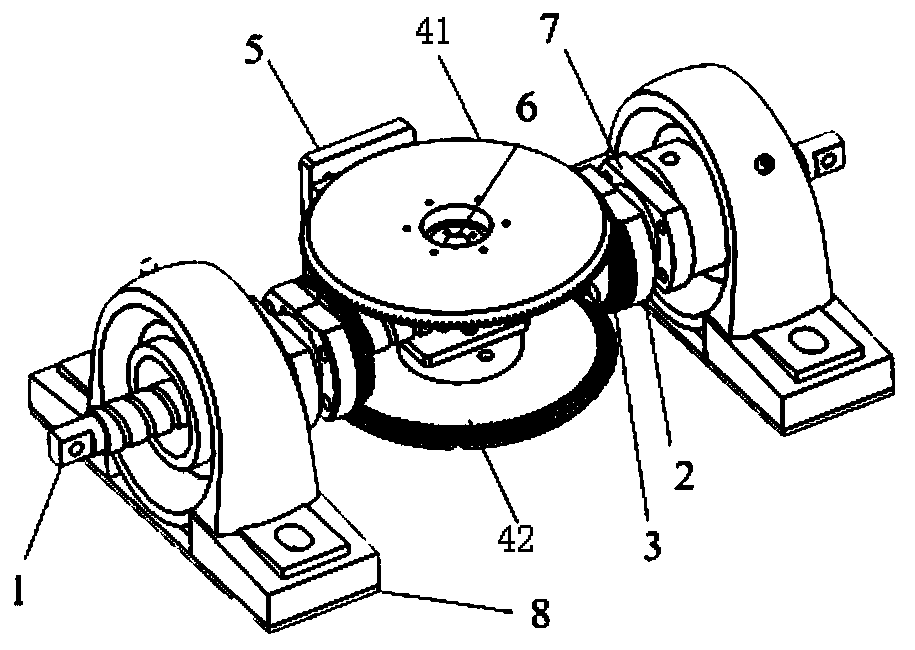
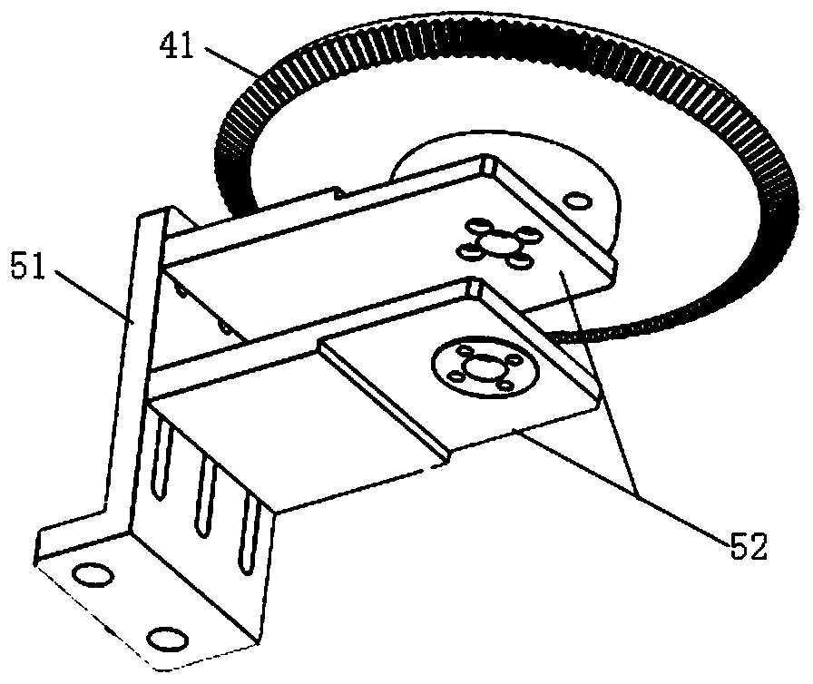
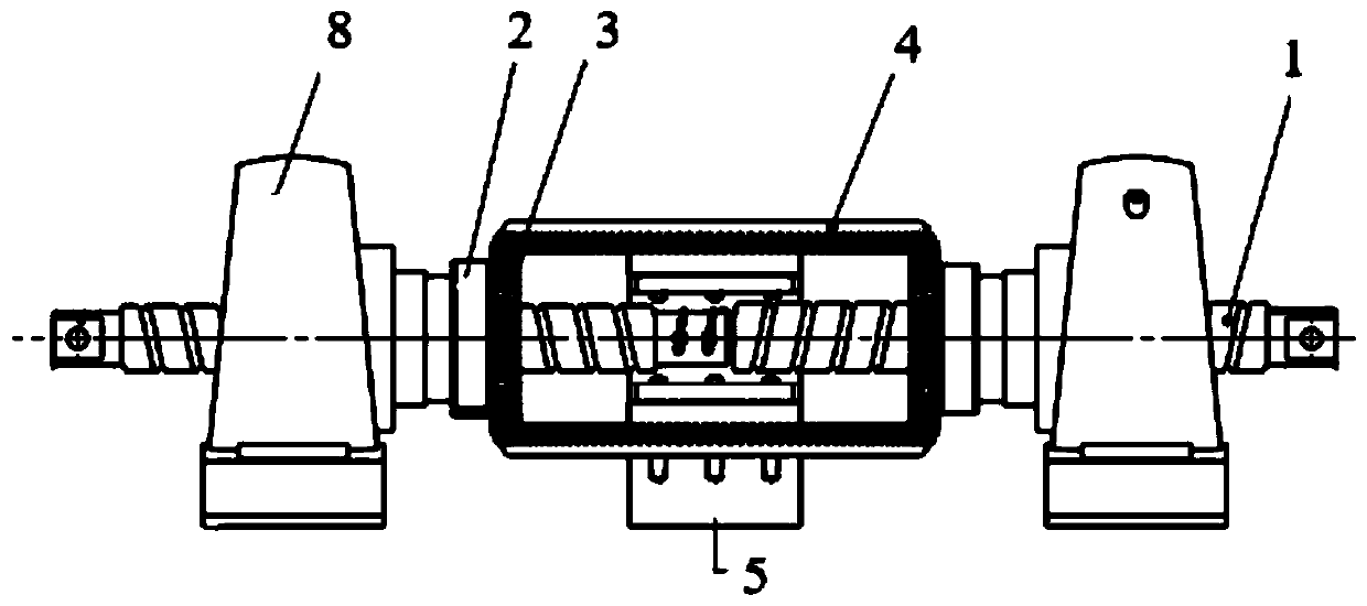
[0026] Such as Figure 1-4 Shown: a modular self-balancing inertial damper, which includes positive and negative tooth screw 1, adapter plate 2, transmission gear 3, main gear 4, bearing plate support 5, central bearing 6, screw nut 7 and support bearing 8; Main gear comprises upper main gear 41 and lower main gear 42;

[0027] The positive and negative tooth screw 1 is a threaded screw, which is divided into two at the midpoint and there are two threads in different directions on both sides of the midpoint, which are respectively the positive tooth end and the negative tooth end; The two sides of the screw rod 1 are symmetrically arranged with the transmission gear 3, the adapter plate 2, and the screw nut 7 respectively from the middle to the end. The disk 2 is rotatably installed on the screw nut connected to the positive and negative screw rod 1, and rotates with the screw nut 7. The hole position of the inner ring of the adapter plate matches the screw nut, and the hole ...


PUM


Abstract

The invention relates to a modular self-balancing inerter damper. Transmission gears, transfer discs and screw rod nuts are sequentially and symmetrically arranged on the two sides of a right-hand threaded and left-hand threaded screw rod from the middle to the end parts correspondingly, the transmission gears are rotationally installed on the screw rod nuts connected with the right-hand threadedand left-hand threaded screw rod through the transfer discs and rotate along with the screw rod nuts, two support bearings are arranged at the two ends of the right-hand threaded and left-hand threaded screw rod in a sleeving mode respectively and connected with the screw rod nuts to serve as fixed supports of the damper; and a bearing plate support is located on the middle position of the right-hand threaded and left-hand threaded screw rod, and an upper main gear and a lower main gear are respectively arranged on a central bearing at the upper part of a bearing plate and under a central bearing at the lower part of the bearing plate, and are respectively connected with the central bearing and the bearing plate through bolts. According to the modular self-balancing inerter damper, a maingear rotates around the axis in the opposite rotation direction through the right-hand threaded and left-hand threaded screw rod, the electromagnetic force and the counter-acting force of the electromagnetic force act on the screw rod in the equivalent opposite direction, the torques in the rotation direction around the axis are mutually offset, and the self-balancing performance of the screw rodis achieved.

Description

technical field [0001] The application relates to the field of civil engineering, in particular to a modular self-balancing inertial damper. Background technique [0002] As a new and efficient structural passive vibration control means, the inertial damper is an energy dissipation and vibration reduction device made of the damping effect of eddy current. It has non-contact, no mechanical friction and loss, no lubrication, long service life, and easy installation. At present, the eddy current damper is mainly used as the damping element of the tuned mass damper and is gradually being applied in the field of passive vibration control of civil engineering structures. [0003] According to the principle of eddy current, the generation of eddy current damping must have the conductor plate to cut the magnetic induction line movement, that is, there is relative motion between the magnetic field source and the conductor plate, and the magnitude of the electromagnetic force generat...

Claims


Application Information

Patent Timeline
Patent Type & Authority Applications(China)
IPC IPC(8): E04B1/98E04B1/36E04H9/02
CPCE04B1/36E04B1/98E04H9/021
Inventor 谢丽宇濮昱薛松涛
Owner TONGJI UNIV
Why Eureka
Try Eureka