Rotation detection device

A technology of rotation detection and induction coil, which is applied in the direction of measuring device, measuring capacity, liquid/fluid solid measurement, etc., can solve the problems of distance limitation, poor anti-interference ability, magnetic sensor permanent magnet interference, etc., to improve distance and save space and cost effects

Pending Publication Date: 2020-05-19
HANGZHOU WEIFENG INTELLIGENT TECH CO LTD
View PDF1 Cites 7 Cited by
  • Summary
  • Abstract
  • Description
  • Claims
  • Application Information

AI Technical Summary

Problems solved by technology

However, since the external strong magnetic field can easily disturb the state of the magnetic sensor, this method has poor anti-interference ability
[0005] The second type, such as the Chinese patent discloses an invention patent with the patent number ZL200680007522.8 and the patent name is an inductive angle sensor. This invention solves the problem that traditional magnetic sensors are easily interfered by permanent magnets.
However, the output signal of the secondary coil is directly output to the comparator. Since the output signal of the secondary coil is induced by the rotation of the metallized disc, the signal itself is relatively weak, so the way of directly outputting the information to the comparator will not The distance between the metallized disc and the rotation counter module is greatly limited, and the two need to have a relatively close distance, and a little distance will greatly affect the detection results

Method used


Image

  • Rotation detection device
  • Rotation detection device
  • Rotation detection device

Examples


Embodiment Construction

[0031] The present invention will be described in further detail below in conjunction with the accompanying drawings and specific embodiments.

[0032] The following will clearly and completely describe the technical solutions in the embodiments of the present invention with reference to the accompanying drawings in the embodiments of the present invention. Obviously, the described embodiments are only some, not all, embodiments of the present invention. Based on the embodiments of the present invention, all other embodiments obtained by persons of ordinary skill in the art without making creative efforts belong to the protection scope of the present invention.

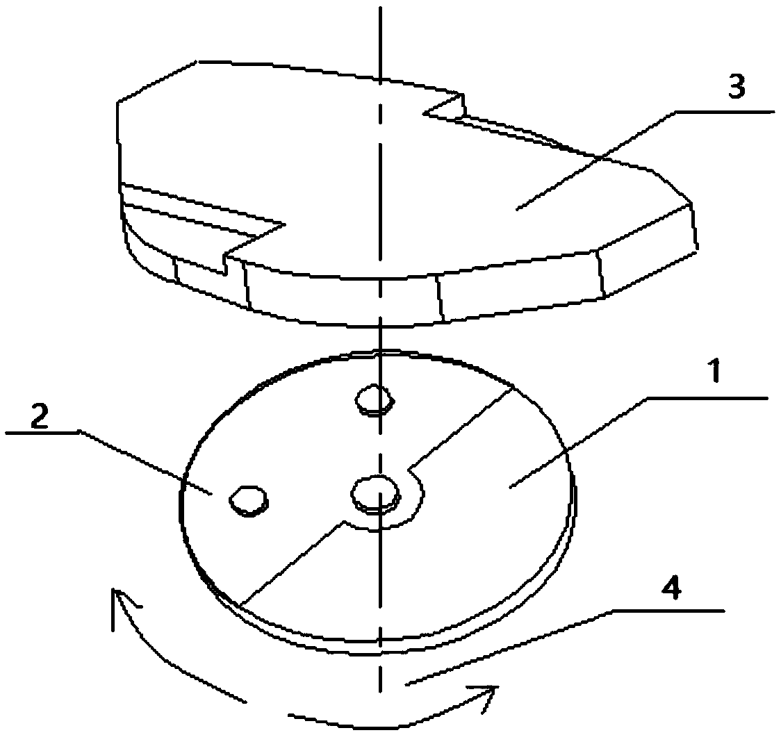
[0033] Such as figure 1 As shown, when the liquid or gas flows, the mechanical transmission part will drive the tray 1 to rotate around its axis 4, and the tray 1 will rotate clockwise or counterclockwise according to the actual flow direction of the liquid or gas. The tray 1 can be a circular tray or a non-circular t...


PUM


Abstract

The invention discloses a rotation detection device. The device comprises a tray which rotates around an axis, and a rotation detection module which is located above the tray and is fixed. An upper surface of the tray is in a partial metallization state; the rotation detection module comprises an excitation circuit, a PCB coil and a signal processing circuit which are connected in sequence; the PCB coil comprises an exciting coil which is parallel to an upper plane of the tray and whose a circle center is positioned on the axis, and a plurality of induction coils which are circumferentially arranged in the exciting coil at equal angles; opposite angles of the plurality of induction coils are matched in pairs; and the signal processing circuit comprises a switch amplifying circuit and a sampling circuit connected to a sampling end of the switch amplifying circuit, and one end of each induction coil is connected to an input end of the switch amplifying circuit. The switch amplifying circuit can amplify induction signals of the induction coil, and the maximum distance between the upper plane of the tray and the PCB coil plane is increased.

Description

technical field [0001] The invention relates to the fluid metering fields such as liquid metering and gas metering, and in particular to a rotation detection device. Background technique [0002] In current fluid metering applications, the most common way is to detect the flow rate or flow rate of liquid or gas based on the rotation of mechanical parts driven by fluid or gas flow. Among them is a rotation detection device, which is used to count the number of rotations of mechanical parts to convert the flow into a digital signal. [0003] There are several common rotation detection methods in fluid metering in the prior art: [0004] The first type uses a magnetic sensor, usually placing a small permanent magnet near the side of the rotor. The permanent magnet rotates around the axis, and a magnetic sensor such as a reed switch is placed above the rotation path of the permanent magnet to convert the change of the magnetic field state into an electrical signal. However, si...

Claims


Application Information

Patent Timeline
Patent Type & Authority Applications(China)
IPC IPC(8): G01F15/075
CPCG01F15/0755
Inventor 谢巍毛国文葛永兵
Owner HANGZHOU WEIFENG INTELLIGENT TECH CO LTD
Why Eureka
Try Eureka