Radar image rapid generation and zooming method

A radar image, fast technology, applied in the direction of image enhancement, image analysis, image data processing, etc., can solve the problems of time-consuming, large computing resources, high computer requirements, etc., to achieve the effect of avoiding calculation and fast cropping

Pending Publication Date: 2020-05-19
CSSC SYST ENG RES INST
View PDF26 Cites 1 Cited by
  • Summary
  • Abstract
  • Description
  • Claims
  • Application Information

AI Technical Summary

Problems solved by technology

This process will consume a lot of computing resources

Method used


Image

  • Radar image rapid generation and zooming method
  • Radar image rapid generation and zooming method
  • Radar image rapid generation and zooming method

Examples


Embodiment Construction

[0056] The following will combine Figure 1 to Figure 2 The method of the present invention is described in detail, which is an optional embodiment of the present invention, and it can be considered that those skilled in the art can modify and polish it within the scope of not changing the spirit and content of the present invention.

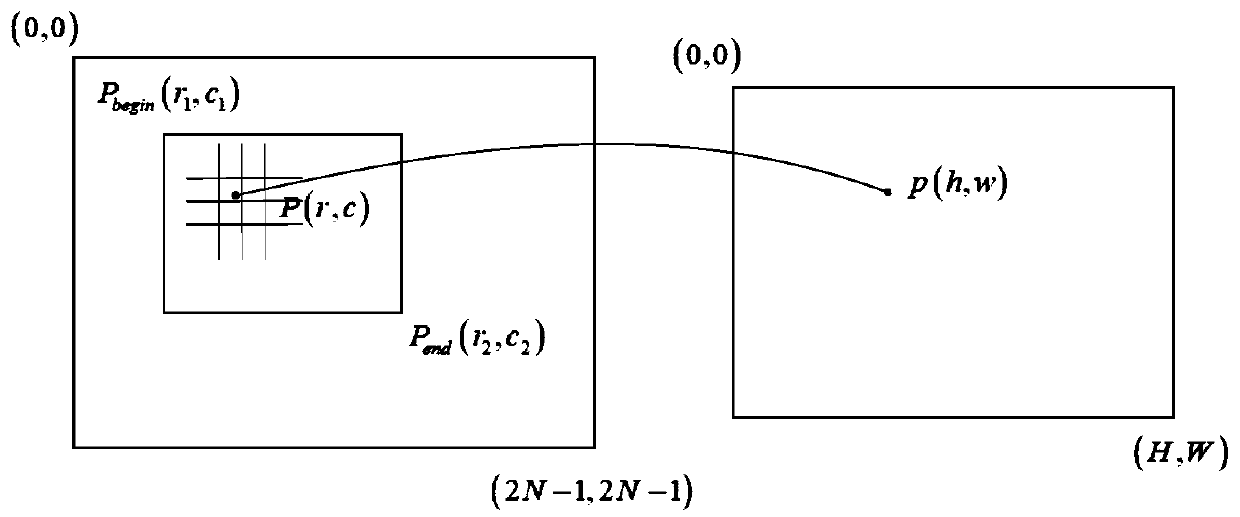
[0057] Step 1: Establish a conversion relationship between radar echo data and radar images through the mapping of radar echo signals and radar images.

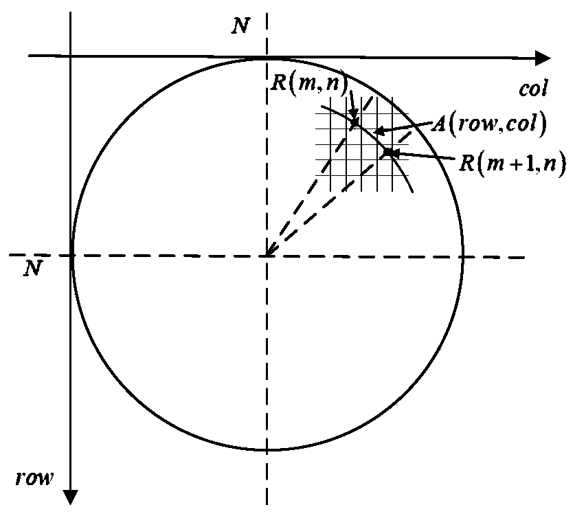
[0058] The radar echo data is the radar echo signal strength data at different distances at an angle obtained after the received radar wave is collected by the acquisition card. If the radar emits radar beams M times in one revolution, and each radar echo collects N points, then the radar echo data collected by the radar in one revolution is an M×N matrix. Among them, the row represents the angle, and the column represents the distance, that is, the radar echo data is in polar coordinate form ...


PUM


Abstract

The invention provides a radar image rapid generation and zooming method, belongs to the field of radar signal processing, and particularly relates to a method for generating a radar image by adoptinga rapid coordinate transformation method and completing rapid zooming of the radar image by adopting a method of directly processing a conversion matrix. The method comprises the steps: establishinga conversion relationship between radar echo data and the radar image through mapping of the radar echo signal and the radar image; and reversely solving a radar image mapping table according to the conversion relation and a radar detection mechanism, reducing the calculation amount of radar image generation, and realizing rapid conversion from the radar echo data to the radar image. Tthe rapid zooming method for establishing the radar image mapping table realizes local detail amplification of the radar image and preview of the whole image and does not lose local detail information while further reducing the calculation amount.

Description

technical field [0001] The invention belongs to the field of radar signal processing, and in particular relates to adopting a fast coordinate transformation method to generate a radar image, and adopting a method of directly processing a conversion matrix to complete rapid zooming of the radar image. Background technique [0002] The P display interface of traditional navigation radar generally adopts the binary display method, which is suitable for detecting targets with large reflection areas on the sea and strong radar echo signals. When the radar echo signal strength is greater than a certain threshold, the position is mapped to the display Pixels on the interface are set to 1, otherwise they are set to 0. By binarizing the image through the threshold, the amount of computation for generating the P-display interface can be greatly reduced. This approach works well for navigation tasks. [0003] For marine oil spill detection tasks, the radar echo signal in the oil spil...

Claims


Application Information

Patent Timeline
IPC IPC(8): G01S13/89G06T3/40G06T7/10
CPCG01S13/89G06T3/4007G06T7/10G06T2207/10044G06T2207/20132Y02A90/10
Inventor 赵琪王国庆王然娄越赵欣李鑫陈栋王进成方子璇
Owner CSSC SYST ENG RES INST
Why Eureka
Try Eureka