Improved Direct Envelope Inversion and Perturbation Decomposition Inversion Method for Strongly Scattering Media

A strong scattering and inversion technology, applied in seismology, instruments, measuring devices, etc., can solve the problem that the velocity inversion in the strong scattering shielding area does not achieve the desired effect and errors, so as to weaken the overlapping effect, reduce the decomposition error, The effect of improving the inversion quality

Active Publication Date: 2020-12-01
JILIN UNIV
View PDF5 Cites 0 Cited by
  • Summary
  • Abstract
  • Description
  • Claims
  • Application Information

AI Technical Summary

Problems solved by technology

Therefore, in the wavefield superposition region, the direct calculation of the envelope will produce significant errors
In addition, the existing methods for velocity inversion in strong scattering shielding areas have not yet achieved ideal results

Method used


Image

  • Improved Direct Envelope Inversion and Perturbation Decomposition Inversion Method for Strongly Scattering Media
  • Improved Direct Envelope Inversion and Perturbation Decomposition Inversion Method for Strongly Scattering Media
  • Improved Direct Envelope Inversion and Perturbation Decomposition Inversion Method for Strongly Scattering Media

Examples


Embodiment 1

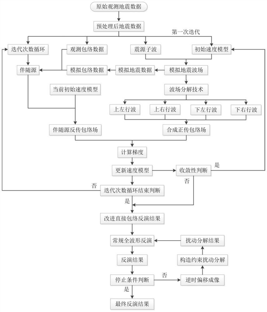
[0072] The overall process of the present invention is as figure 1 shown.

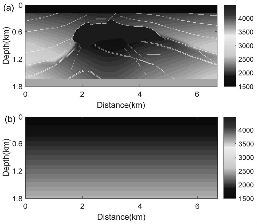
[0073] The real velocity model and the initial velocity model used are as follows figure 2 shown. In the real velocity model, the background velocity is about 2000m / s, including some detailed structures. There is a high-speed salt dome in the upper part of the model, with a velocity of 4482m / s. This model is a typical strong scattering medium model. The initial velocity model adopted is a linearly changing gradient model, and the velocity range is roughly equivalent to the background velocity variation range of the real model.

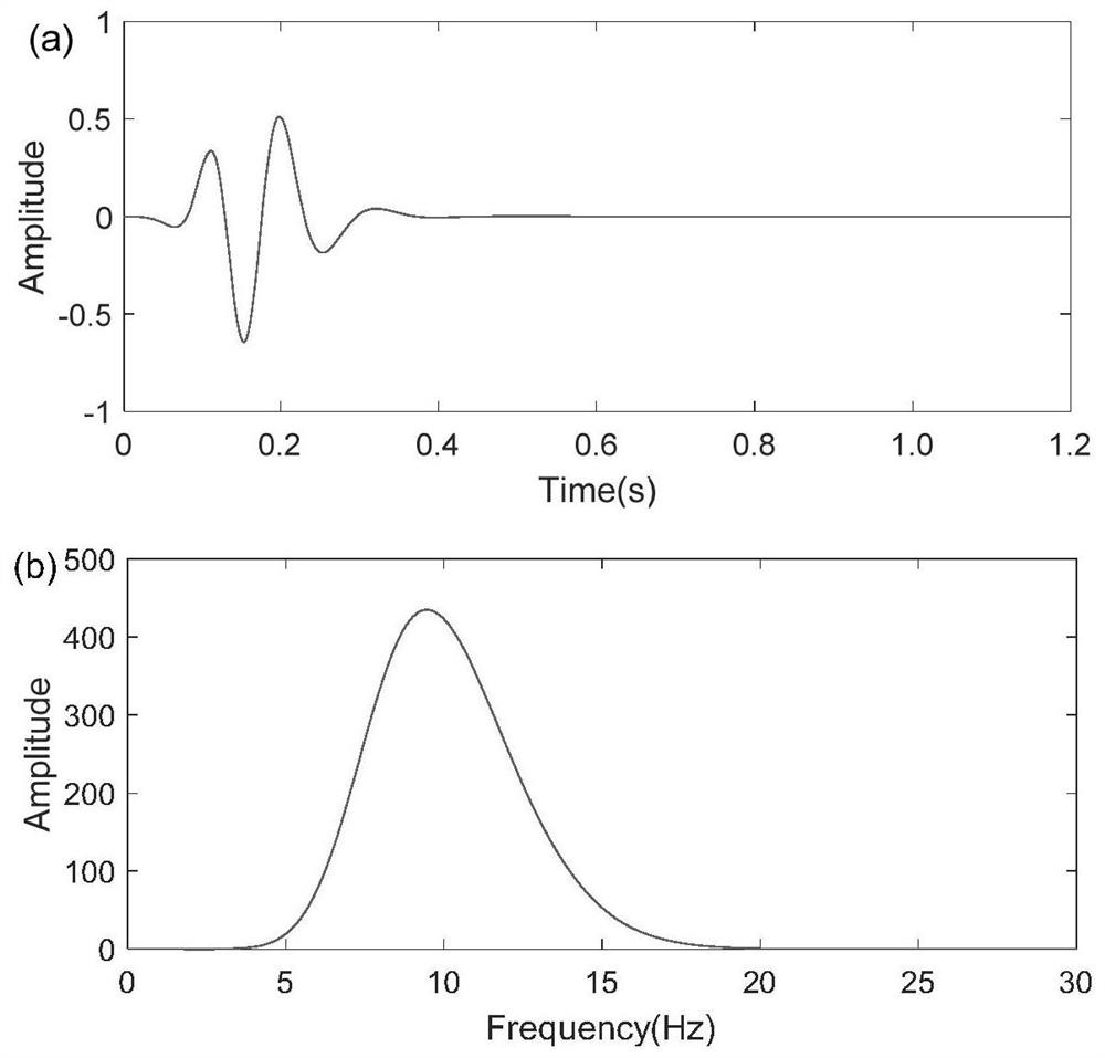
[0074] use as image 3 The source wavelet is shown. In order to simulate the lack of low-frequency information in actual seismic acquisition, high-pass filtering was performed on the Lake wavelet to cut off the low-frequency information below 4 Hz, and the main frequency of the source wavelet was about 9 Hz.

[0075] The conventional direct envelope inversion is performed...


PUM


Abstract

The invention relates to a strong scattering medium inversion method for improving direct envelope inversion and disturbance decomposition. The method is characterized in that envelope operation is nonlinear operation, and a large error exists in envelope field calculation at a wave field overlapping position; the seismic wave field is subjected to up-down and left-right traveling wave decomposition before the forward envelope field is calculated, so influence of wave field overlapping of forward envelope field calculation is effectively relieved; the improved envelope field is substituted into a direct envelope inversion algorithm, namely improved direct envelope inversion, wherein the improved direct envelope inversion can better describe the speed structure of a strong scatterer. Aimingat speed modeling of a strong scattering shielding area, the invention provides a disturbance decomposition method adopting construction constraints; selection of disturbance decomposition parametersis constrained by using the reverse time migration imaging result, so wrong identification of the strong scatterer caused by parameter selection can be avoided. An improved direct envelope inversionmethod and a structure constraint disturbance decomposition method are combined, good strong scatterer speed modeling can be obtained, and a good shielding area speed structure can further be obtained.

Description

Technical field: [0001] The invention relates to a strong scattering medium inversion method which uses an improved direct envelope inversion method to obtain a large-scale structure of a strong scatterer, and uses a structural constraint disturbance decomposition method to obtain the lower boundary of a strong scatterer and the velocity structure of a shielding area. Background technique: [0002] At present, in the field of seismic exploration, the method with the highest velocity modeling accuracy is the full waveform inversion method. The full waveform inversion method regards the velocity inversion problem as an optimization problem with the data residual as the objective function, and usually uses a local optimization algorithm to solve it. The reason why conventional full waveform inversion can be solved by local optimization algorithm is that it uses Born approximation, a weak scattering approximation. This leads to the fact that the conventional full waveform inver...

Claims


Application Information

Patent Timeline
Patent Type & Authority Patents(China)
IPC IPC(8): G01V1/30
CPCG01V1/303G01V2210/32G01V2210/51G01V2210/53G01V2210/6222
Inventor 张盼韩立国
Owner JILIN UNIV
Why Eureka
Try Eureka