
Velocity Modeling Method in Depth Domain

A velocity modeling, depth domain technology, applied in seismology, instruments, measuring devices, etc., can solve the vertical resolution scale, accuracy and seismic reflection imaging mismatch, can not meet the vertical and horizontal accuracy requirements of the velocity model, seismic reflection imaging Vertical scale mismatch and other problems, to achieve the effect of improving imaging quality, imaging accuracy, and speed modeling accuracy

Active Publication Date: 2021-07-20
CHINA PETROLEUM & CHEM CORP +1
View PDF0 Cites 0 Cited by
  • Summary
  • Abstract
  • Description
  • Claims
  • Application Information

AI Technical Summary

Problems solved by technology

The current depth-domain velocity model establishment method is mainly based on seismic velocity analysis, which does not make full use of VSP and logging data information, resulting in a mismatch between the vertical resolution scale and accuracy of the target interval velocity model and seismic reflection imaging, which affects the pre-stack For the imaging accuracy of depth migration, how to combine the velocity of acoustic logging and seismic processing analysis to establish a high-precision depth-domain velocity model is of great significance for improving the accuracy of migration
[0003] In the conventional prestack depth migration imaging process, the velocity model obtained by seismic processing analysis has the problem of mismatching the vertical scale of seismic reflection imaging, which cannot meet the vertical and horizontal accuracy requirements of prestack depth migration imaging for the velocity model. Therefore, we invented a new depth-domain velocity modeling method to solve the above technical problems

Method used


Image

  • Velocity Modeling Method in Depth Domain
  • Velocity Modeling Method in Depth Domain
  • Velocity Modeling Method in Depth Domain

Examples


Embodiment Construction

[0023] In order to make the above and other objects, features and advantages of the present invention more comprehensible, the preferred embodiments are listed below and shown in the accompanying drawings in detail as follows.

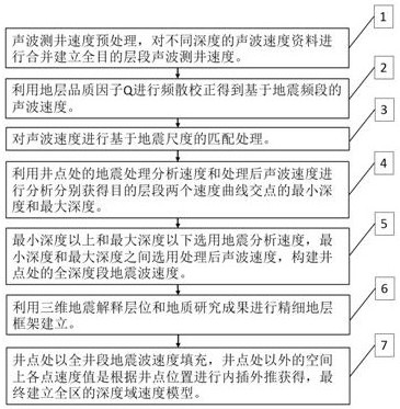
[0024] Such as figure 1 as shown, figure 1 It is a flow chart of the depth-domain velocity modeling method of the present invention.

[0025] Step 1: Acoustic logging velocity preprocessing, merging the acoustic logging velocities at different depths to establish the acoustic logging velocity for all target intervals;

[0026] The sonic logging velocity preprocessing includes the determination, merging and unified processing of depth sampling in different acquisition intervals of repeated depth ranges.

[0027] If there is a deviation of more than 10% in the borehole diameter, it is necessary to correct the borehole diameter of the acoustic logging velocity to eliminate the deviation of the acoustic logging velocity caused by the large deviation of t...


PUM


Abstract

The present invention provides a velocity modeling method in the depth domain, which includes: performing acoustic logging velocity preprocessing; using the formation quality factor Q to perform dispersion correction to obtain the acoustic velocity based on the seismic frequency band; performing matching processing on the acoustic velocity based on the seismic scale; Use the seismic processing analysis velocity at the well point and the processed acoustic wave velocity to obtain the minimum depth and maximum depth of the intersection point of the two velocity curves in the target layer; construct the seismic wave velocity in the full depth section; comprehensively apply seismic interpretation and geological research results to establish Fine stratigraphic frame model: Under the control of the fine stratum frame model, the seismic wave velocity in the full depth section is used as the conditional data, and the seismic processing analysis velocity is used as the trend constraint to perform fine interpolation to realize the smooth vertical and horizontal transition of the velocity and establish the depth domain velocity of the whole region Model. The depth-domain velocity modeling method improves the vertical accuracy and lateral accuracy of the depth-domain velocity model, thereby improving the depth migration imaging quality of complex structures.

Description

technical field [0001] The invention relates to the technical field of seismic data processing, in particular to a velocity modeling method in depth domain. Background technique [0002] With the continuous improvement of computer computing power, pre-stack depth migration has gradually become an important means to solve the imaging accuracy of complex structures. Kirchhoff depth migration, one-way wave finite difference depth migration and two-way wave reverse time depth migration, etc. There are more and more methods being used, and a large number of pre-stack depth migration application examples show that the accuracy of the depth-domain velocity model directly determines the effect of depth migration, especially the reverse time depth migration algorithm. The current depth-domain velocity model establishment method is mainly based on seismic velocity analysis, which does not make full use of VSP and logging data information, resulting in a mismatch between the vertical r...

Claims


Application Information

Patent Timeline
Patent Type & Authority Patents(China)
IPC IPC(8): G01V1/36G01V1/28G01V1/50
CPCG01V1/282G01V1/362G01V1/50G01V2210/512
Inventor 孔庆丰张学涛赵茂强毕丽飞孙卫国张玉晓田坤
Owner CHINA PETROLEUM & CHEM CORP
Learn More