Building with rescue function

A building and functional technology, applied in the field of buildings with fire-fighting and rescue functions, can solve problems such as difficulty in putting out high-rise buildings

Pending Publication Date: 2020-05-22
吴旭榕
View PDF5 Cites 0 Cited by
  • Summary
  • Abstract
  • Description
  • Claims
  • Application Information

AI Technical Summary

Problems solved by technology

[0004] The purpose of this application is to solve the diffi...

Method used


Image

  • Building with rescue function
  • Building with rescue function
  • Building with rescue function

Examples


Embodiment Construction

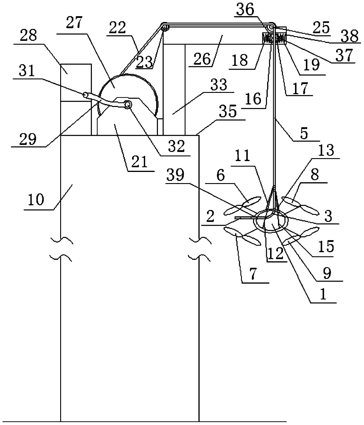
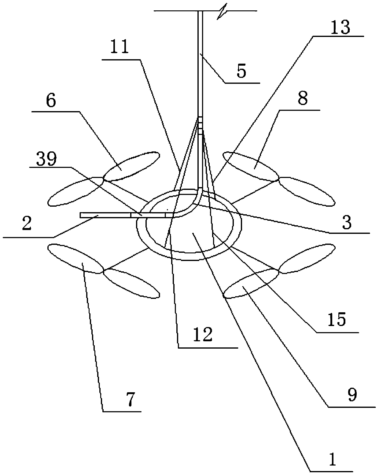
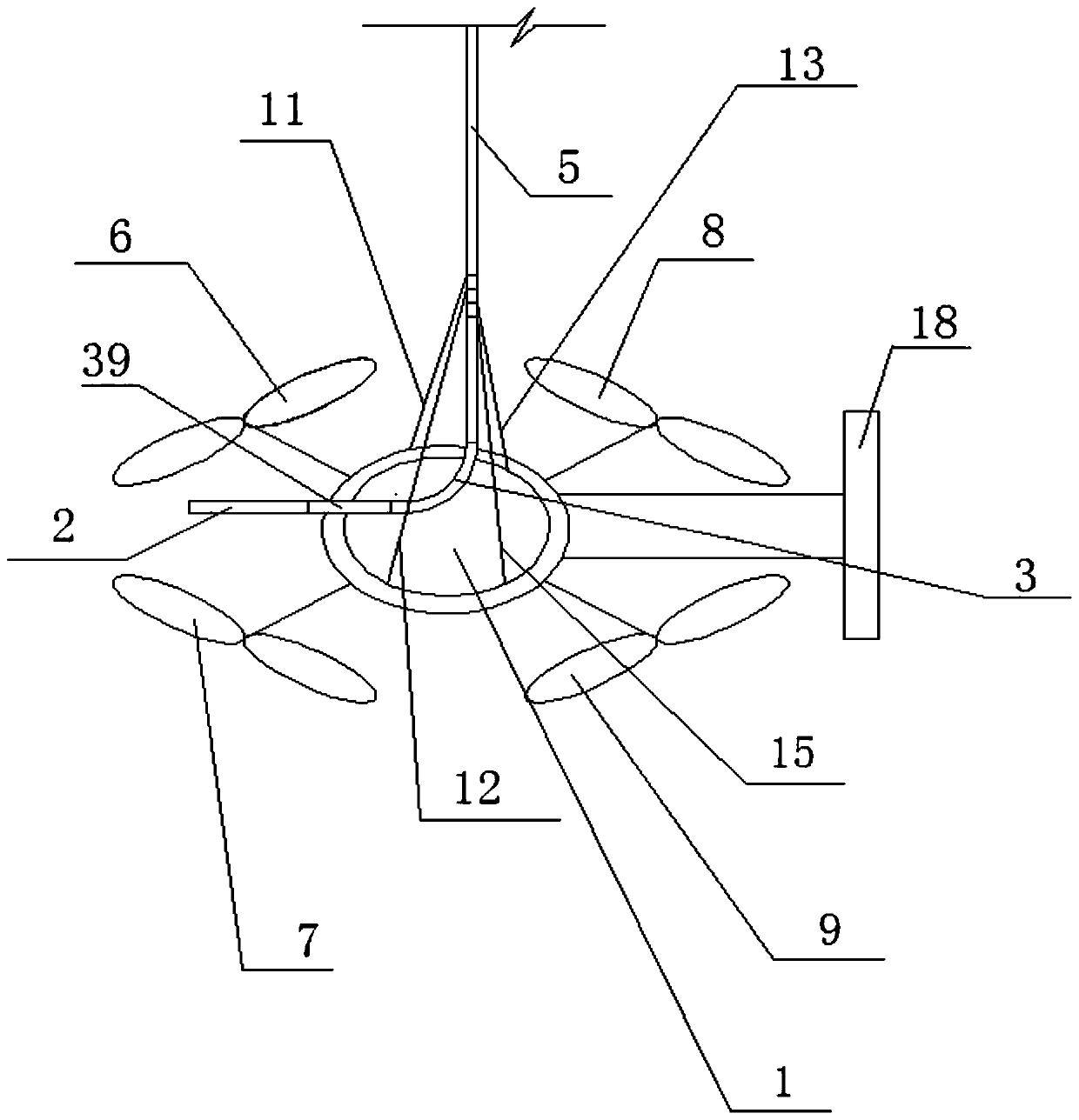
[0065] Such as figure 1 as shown, figure 1 It is a schematic side view of the first embodiment of the present application. The roof 35 of a building 10 with a rescue function is provided with an electric hose reel 21, a cantilever mechanism, and a spraying mechanism. The spraying mechanism includes a support structure 1, a rotating wing 6, a rotating Wing 7, rotary wing 8, and rotary wing 9, the above-mentioned rotary wing 6, rotary wing 7, rotary wing 8, and rotary wing 9 are arranged symmetrically around the supporting structure 1, and the rotary wing 6, rotary wing 7, rotary wing 8, The rotation plane of the rotary wing 9 is parallel to or in the same plane as the spray gun 2, and its structure is similar to that of the existing quadrotor UAV. The support structure 1 is horizontally connected with the spray gun 2, and the cantilever mechanism includes a vertical column 33 and the horizontal cantilever 26, the structure of the bottom plate and side plate of the electric hos...


PUM


Abstract

The invention relates to a building with a rescue function. The building with the rescue function is characterized in that an electric pipe winder, a cantilever mechanism and a spraying mechanism arearranged on a roof or a refuge floor of the building, the spraying mechanism comprises a supporting structure and at least two rotating wings, the rotating wings are distributed on the supporting structure, a spraying gun or a spraying head or a transverse water outlet pipe is transversely connected to the supporting structure, the cantilever mechanism comprises a transverse cantilever, a windingdrum of the electric pipe winder is connected with and wound with a rubber pipe, the rubber pipe wound by the winding drum of the electric pipe winder extends out of the winding drum, extends from theinner side to the outer side of the cantilever and then extends downwards to form a vertical rubber pipe to be connected with a water inlet of the spray gun or the spray head or the transverse wateroutlet pipe, and the supporting structure or the spray gun or the spray head or the transverse water outlet pipe is transversely suspended on the vertical rubber pipe.

Description

technical field [0001] The application belongs to a building with fire fighting and rescue functions. Background technique [0002] At present, there are more and more high-rise and super-high-rise buildings, and the hidden safety hazards of the buildings exist in fact. In critical situations such as breaking out of fire, there are very few effective fire-fighting and rescue means for people, and the fire-extinguishing and life-saving means and the height of fire-fighting and life-saving are also affected. Limitation, the existing technology has appeared the technical scheme of using unmanned aerial vehicle to carry out fire extinguishing. The authorized patent of 2015204461488, the application number of 2014100121434, the authorized patent of application number of 2012105108583. However, this type of product has many disadvantages: for example, high-pressure water supply and pressurization problems in super-high-rise fire extinguishing, water hammer phenomenon and the risk...

Claims


Application Information

Patent Timeline
IPC IPC(8): A62C31/00A62C31/28A62B7/12
CPCA62C31/005A62C31/28A62B7/12A62C99/0072
Inventor 不公告发明人
Owner 吴旭榕
Why Eureka
Try Eureka