Automatic assembling equipment for valve body assembly of reading valve

An automatic assembly and valve body technology, applied in assembly machines, metal processing equipment, metal processing, etc., can solve the problems of high error rate of manual assembly, low efficiency of manual assembly, missing and wrong installation, etc.

Active Publication Date: 2020-05-22
弗瑞斯阀门(宁波)有限公司
View PDF6 Cites 7 Cited by
  • Summary
  • Abstract
  • Description
  • Claims
  • Application Information

AI Technical Summary

Problems solved by technology

In the prior art, the assembly of the temperature-controlled valve body assembly is generally done manually, but there are some disadvantages in the manual assembly of the temperature-controlled valve body assembly: First, the efficiency of manual assembly is low, the labor intensity of the workers is high, and it is easy to Fatigue occurs due to repeated operations; secondly, the error rate of manual assembly is high, and it is prone to missing and wrong installations, resulting in an increase in the number of unqualified products; thirdly, the consistency of manual assembly products is poor, and the quality of different products assembled by different workers is different

Method used


Image

  • Automatic assembling equipment for valve body assembly of reading valve
  • Automatic assembling equipment for valve body assembly of reading valve
  • Automatic assembling equipment for valve body assembly of reading valve

Examples


Embodiment Construction

[0061] The present invention will be described in further detail below in conjunction with the accompanying drawings.

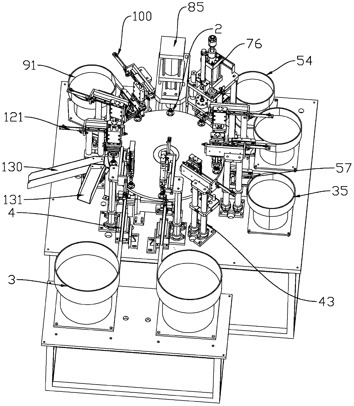
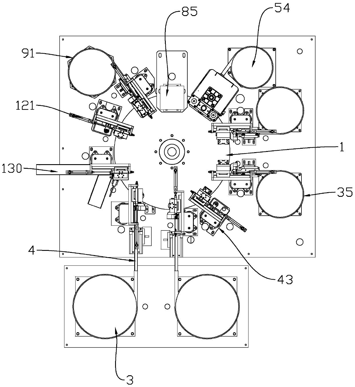
[0062] Such as figure 1 with 2 As shown, the present invention mainly includes a turntable 1, a first valve body feeding mechanism, a first valve body feeding mechanism, an oiling mechanism for an inner hole and an outer ring of the valve body, a first plastic inner ring feeding mechanism, a second plastic inner ring feeding mechanism, a roller Flower inner ring feeding mechanism, valve body closing mechanism, O-ring feeding mechanism, O-ring outer ring oiling mechanism and unloading mechanism.

[0063] Such as figure 1As shown, a plurality of bearing seats 2 are detachably connected to the turntable 1 through connectors, and the plurality of bearing seats 2 are evenly distributed along the circumferential direction of the turntable 1. During the assembly process of the reading valve valve body assembly, the plurality of bearing seats 2 are used for Carry ...


PUM


Abstract

The invention relates to automatic assembling equipment, in particular to automatic assembling equipment for a valve body assembly of a reading valve. The automatic assembling equipment comprises a rotating disc, a first valve body feeding mechanism, a second valve body feeding mechanism, a valve body inner hole outer ring oiling mechanism, a first plastic inner ring feeding mechanism, a second plastic inner ring feeding mechanism, a knurled inner ring feeding mechanism, a valve body closing mechanism, an O-shaped ring feeding mechanism, an O-shaped ring outer ring oiling mechanism and a discharging mechanism, wherein the first valve body feeding mechanism, the second valve body feeding mechanism, the valve body inner hole outer ring oiling mechanism, the first plastic inner ring feeding mechanism, the second plastic inner ring feeding mechanism, the knurled inner ring feeding mechanism, the valve body closing mechanism, the O-shaped ring feeding mechanism, the O-shaped ring outer ringoiling mechanism and the discharging mechanism are sequentially arranged around the rotary disc in the circumferential direction. According to the automatic assembling equipment for the valve body assembly of the reading valve, by arranging a series of assembling mechanisms around the rotary disc, the assembling work of the valve body assembly of the reading valve can be automatically, accuratelyand reliably completed, and the assembling work efficiency is improved.

Description

technical field [0001] The invention relates to an automatic assembly device, in particular to an automatic assembly device for a valve body assembly of a reading valve. Background technique [0002] The balance valve is a valve with special functions. There is nothing special about the valve itself, the only difference lies in the function and place of use. In some industries, due to the large pressure difference or flow difference of the medium (all kinds of flowable substances) in various parts of the pipeline or container, in order to reduce or balance the difference, between the corresponding pipelines or containers A valve is installed to adjust the relative balance of the pressure on both sides, or to achieve flow balance through the method of shunting. The valve is called a balance valve. In order to accurately measure the data in the balance valve, it is necessary to use a reading valve that is convenient for measuring data. [0003] The assembly of the valve body...

Claims


Application Information

Patent Timeline
Patent Type & Authority Applications(China)
IPC IPC(8): B23P21/00B23P19/027B07C5/34B07C5/36
CPCB07C5/34B07C5/362B23P19/001B23P19/002B23P19/007B23P19/027B23P21/006
Inventor 克劳斯·弗瑞斯
Owner 弗瑞斯阀门(宁波)有限公司
Why Eureka
Try Eureka