Protective cover and vehicle with same
A technology for a protective cover and a vehicle is applied in the field of the protective cover and the vehicle having the same, which can solve the problems of inconvenient installation of the protective cover and the like.
Active Publication Date: 2020-05-22
BEIJING XIAOMA ZHIXING TECH CO LTD
6 Cites 2 Cited by
AI-Extracted Technical Summary
Problems solved by technology
[0004] The main purpose of the present invention is to provide a protective cover and a vehicle w...
Method used
In order to improve the protection effect to the 3rd radar and the 4th radar, the 3rd cover body 3 is provided with the first protruding part 33 that extends along the second direction, and the first protruding part 33 protrudes from the second cover body 2 Setting; the fourth cover body 4 is provided with a second protruding portion 43 extending along the second direction, and the second protruding portion 43 protrudes from the second cover body 2; between the first protruding portion 33 and the second protruding portion 43 An avoidance gap 16 is formed. By arranging the first protruding portion 33 and the second protruding portion 43, the aerodynamic performance of the entire protective cover can be improved, and the wind resistance of the protective cover can be reduced. The escape gap 16 formed between the first protruding portion 33 and the second protruding portion 43 can avoid the field of view of the second radar and ensure the reliability of the second radar.
In the present embodiment, the first cut plane 13 is four, and four first cut planes 13 surround the first field of view channel, and the cross-sectional area of the first field of view channel increases gradually along the first direction; There are four second cut planes 22, and the four second cut planes 22 enclose the second viewing field channel, and the cross-sectional area of the second viewing field channel gradually increases along the second direction, thereby improving the avoidance effect.
Specifically, the protective cover is provided with a first recess 35 and a second recess 45, the first GPS antenna mounting hole 34 extends to the first recess 35, and the second GPS antenna mounting hole 44 extends to the second recess Section 45. By setting the first concave portion 35, the first GPS antenna can be avoided, so that the first GPS antenna forms a structure embedded in the first concave portion 35, which is conducive to improving the positioning and protection effect of the first GPS antenna; Similarly, by setting the second recessed portion 45, the second GPS antenna can be avoided, so that the second GPS antenna forms a structure embedded in the second recessed portion 45, which is conducive to improving the positioning and positioning of the second GPS antenna. protective effect.
The first protrusion 33 is provided with a third slot, and the second protrusion 43 is provided with a fourth slot; the protective cover includes the fifth cover body 5 spliced with the first protrusion 33 and the second protrusion The sixth cover body 6 spliced by part 43; the fifth cover body 5 is provided with the fifth slot, and t...
Abstract
The invention provides a protective cover and a vehicle with the protective cover. The protective cover is used for being mounted at the top of the vehicle, and the protective cover comprises a firstcover body and a second cover body which are spliced with each other. A first radar mounting hole is formed in the side, away from the second cover body, of the first cover body and faces a first direction. The first cover body is further provided with a first open slot. A second radar mounting hole is formed in the side, away from the first cover body, of the second cover body, the second radar mounting hole is formed in a second direction, and a second open slot is further formed in the second cover body. The first direction and the second direction are opposite. The first open slot and thesecond open slot are spliced to form a visual inspection device mounting hole for mounting a visual inspection device. According to the protective cover, the problem that an existing protective coveris inconvenient to install is solved, and the installation precision of equipment such as a first radar, a second radar and the visual detection device can be ensured, and the data acquisition accuracy is improved.
Application Domain
Antenna adaptation in movable bodiesRadiating element housings +1
Technology Topic
Automotive engineeringStructural engineering +6
Image
Examples
- Experimental program(1)
Example Embodiment
[0032] It should be noted that the embodiments in the application and the features in the embodiments can be combined with each other if there is no conflict. Hereinafter, the present invention will be described in detail with reference to the drawings and in conjunction with the embodiments.
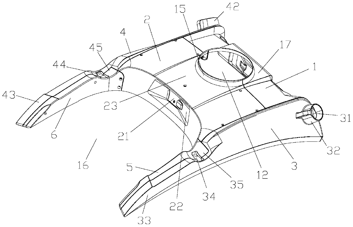
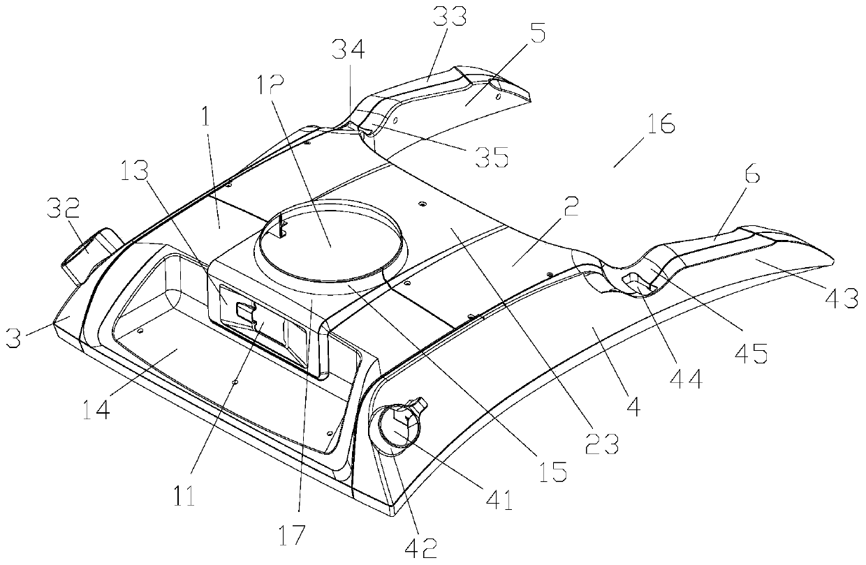
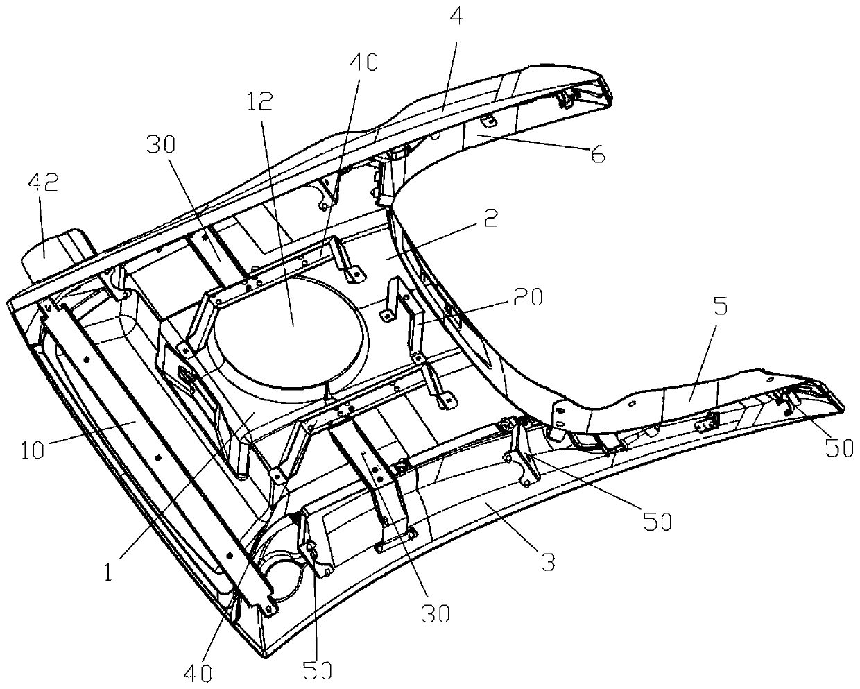
[0033] Please refer to Figure 1 to Figure 6 The present invention provides a protective cover, which is used to install on the top of a vehicle. The protective cover includes a first cover body 1 and a second cover body 2 that are spliced with each other; the first cover body 1 is away from the second cover body 2 One side is provided with a first radar mounting hole 11, and the first radar mounting hole 11 is set toward the first direction; the first cover 1 is also provided with a first slot; the second cover 2 is away from one side of the first cover 1 A second radar mounting hole 21 is provided on the side, and the second radar mounting hole 21 is set toward the second direction, and the second cover 2 is also provided with a second slot; wherein the first direction and the second direction are opposite directions; The first slot and the second slot are spliced to form a visual inspection device mounting hole 12 for mounting the visual inspection device.
[0034] The protective cover of the present invention is used to install on the top of a vehicle. The protective cover includes a first cover body 1 and a second cover body 2 which are spliced with each other; the first cover body 1 is provided with a first radar on the side away from the second cover body 2 Mounting hole 11, the first radar mounting hole 11 is set toward the first direction; the first cover 1 is also provided with a first slot; the second cover 2 is provided with a second radar mounting on the side away from the first cover 1 Hole 21, the second radar mounting hole 21 is set toward the second direction, and the second cover 2 is also provided with a second slot; wherein the first direction and the second direction are opposite directions; the first slot and the second Slotted and spliced to form a visual inspection device mounting hole 12 for mounting the visual inspection device. When the protective cover is used, the first cover body 1 and the second cover body 2 are spliced together. When the first cover body 1 and the second cover body 2 are relatively close together, a part of the first radar passes through the first radar mounting hole 11 Pass out to the outside of the first cover 1, a part of the second radar passes through the second radar mounting hole 21 to the outside of the second cover 2, and a part of the visual inspection device passes through the visual inspection device mounting hole 12 to the protection The outside of the hood. In this way, the protection of the first radar, the second radar, and the visual detection device can be realized without disassembling the first radar, the second radar, and the visual detection device, and the installation is convenient, which solves the inconvenient installation of the protective cover in the prior art. Problem; and can ensure the installation accuracy of the first radar, the second radar, and the visual detection device, and improve the accuracy of data collection.
[0035] Specifically, the first direction is a direction toward the front of the vehicle, the second direction is a direction toward the rear of the vehicle, and the third direction is a direction toward the left or right of the vehicle. The vision detection device is used to obtain image information around the vehicle, and includes a detection camera; preferably, a radar is provided on the top of the vision detection device.
[0036] In order to reduce the interference of the protective cover to the operation of the first radar and/or the second radar, the first cover 1 is provided with a first cut surface 13 for avoiding the field of view of the first radar; the first cut surface 13 is Multiple, multiple first cut planes 13 are arranged around the first radar mounting hole 11; and/or, the second cover 2 is provided with a second cut surface 22 for avoiding the field of view of the second radar; 22 is a plurality, and a plurality of second cut surfaces 22 are arranged around the second radar mounting hole 21.
[0037] In this embodiment, there are four first cut planes 13 and the four first cut planes 13 enclose the first field of view channel, and the cross-sectional area of the first field of view channel gradually increases along the first direction; the second cut plane 22 There are four, and the four second tangent surfaces 22 enclose the second field of view channel, and the cross-sectional area of the second field of view channel gradually increases along the second direction, thereby improving the avoidance effect.
[0038] In addition, in order to further reduce the interference to the operation of the first radar and ensure that the field of view of the first radar is open, the first cover 1 is provided with a groove 14 which is located at the first radar mounting hole 11 away from the second cover One side of the body 2 avoids the field of view of the first radar through the groove portion 14.
[0039] Specifically, the first cover body 1 is provided with a first flange arranged along the edge of the first slot, and the second cover body 2 is provided with a second flange arranged along the edge of the second slot. The rim and the second flange are spliced to form a first annular flange 15; in the direction away from the main part of the shield, the aperture of the inner hole of the first annular flange 15 is gradually reduced. In this way, it can better fit with the visual inspection device, which is beneficial to drain the rainwater flowing down the side wall of the visual inspection device.
[0040] The protective cover includes a third cover body 3 and a fourth cover body 4. The third cover body 3 and the fourth cover body 4 are spaced apart along a third direction, and the third direction is perpendicular to the first direction and the second direction; The body 1 and the second cover body 2 are located between the third cover body 3 and the fourth cover body 4; the third cover body 3 is spliced with the first cover body 1 and the second cover body 2, and the fourth cover body 4 and The first cover body 1 and the second cover body 2 are spliced together; wherein, the third cover body 3 is provided with a third radar mounting hole 31; the fourth cover body 4 is provided with a fourth radar mounting hole 41. When installing, align the third radar mounting hole 31 of the third cover 3 with the third radar, and then splice the third cover 3 with the first cover 1 and the second cover 2; the fourth cover 4 The fourth radar mounting hole 41 is aligned with the fourth radar, and then the fourth cover is spliced with the first cover 1 and the second cover 2 to complete the assembly of the third cover 3 and the fourth cover 4. There is no need to disassemble the third radar and the fourth radar, which effectively facilitates the installation of the protective cover and ensures the working accuracy of the third radar and the fourth radar.
[0041] Specifically, the third cover body 3 is provided with a second annular flange 32 arranged around the third radar mounting hole 31, and the second annular flange 32 is convexly arranged toward the side of the protective cover away from the vehicle, and the second annular flange The inner wall of 32 is provided with a first wiring groove, and the first wiring groove extends toward the main body of the third cover 3; the fourth cover 4 is provided with a third ring that surrounds the fourth radar mounting hole 41 The flange 42, the third annular flange 42 is convexly arranged toward the side of the protective cover away from the vehicle, the inner wall of the third annular flange 42 is provided with a second wiring groove, and the second wiring groove faces the fourth cover body The main part of 4 is extended.
[0042] In order to improve the protection effect of the third radar and the fourth radar, the third cover 3 is provided with a first protrusion 33 extending in the second direction, and the first protrusion 33 is protruding from the second cover 2; The fourth cover 4 is provided with a second protrusion 43 extending in the second direction, and the second protrusion 43 protrudes from the second cover 2; an escape gap is formed between the first protrusion 33 and the second protrusion 43 16. By providing the first protrusion 33 and the second protrusion 43, the aerodynamic performance of the entire protective cover can be better, and the wind resistance of the protective cover can be reduced. The avoidance gap 16 formed between the first protrusion 33 and the second protrusion 43 can avoid the field of view of the second radar, and ensure the working reliability of the second radar.
[0043] The first protrusion 33 is provided with a third slot, and the second protrusion 43 is provided with a fourth slot; the protective cover includes a fifth cover 5 spliced with the first protrusion 33 and a second protrusion 43 spliced The sixth cover 6; the fifth cover 5 is provided with a fifth slot, the third slot and the fifth slot are spliced to form the first GPS antenna mounting hole 34; the sixth cover 6 is provided with a sixth Slotted, the fourth slot and the sixth slot are spliced to form the second GPS antenna mounting hole 44. In this way, when the first protrusion 33 and the fifth cover 5 are assembled together, the third slot and the fifth slot form the first GPS antenna mounting hole 34, which limits a part of the first GPS antenna to the first GPS antenna. In the GPS antenna mounting hole 34; when the second protrusion 43 and the sixth cover 6 are being assembled, the fourth slot and the sixth slot are spliced to form a second GPS antenna mounting hole 44, and the second GPS antenna A part is restricted in the second GPS antenna mounting hole 44. The installation process does not require disassembly of the first GPS antenna and the second GPS antenna, which effectively facilitates the assembly of the protective cover and helps ensure the accuracy of the installation of the first GPS antenna and the second GPS antenna, thereby ensuring that the first GPS antenna and the The working accuracy of the second GPS antenna.
[0044] Specifically, the protective cover is provided with a first recess 35 and a second recess 45, the first GPS antenna mounting hole 34 extends to the first recess 35, and the second GPS antenna mounting hole 44 extends to the second recess 45. By providing the first recess 35, the first GPS antenna can be avoided, so that the first GPS antenna has a structure embedded in the first recess 35, which is beneficial to improve the positioning and protection effect of the first GPS antenna; Similarly, by providing the second recessed portion 45, the second GPS antenna can be avoided, so that the second GPS antenna has a structure embedded in the second recessed portion 45, which is beneficial to improve the positioning and positioning of the second GPS antenna. Protection effect.
[0045] A first raised portion 17 is provided on the first cover body 1, and the first raised portion 17 is raised toward the side of the first cover body 1 away from the vehicle, and the first slot is provided on the first raised portion 17; The second cover body 2 is provided with a second convex portion 23, the second convex portion 23 is convexly disposed toward the side of the second cover body 2 away from the vehicle, and the second slot is disposed on the second convex portion 23. By providing the first protrusion 17 and the second protrusion 23, the structural strength at the corresponding positions of the first cover body 1 and the second cover body 2 can be effectively improved, that is, the first slot and the second slot can be guaranteed The structural strength at the location to avoid deformation at the splicing location. Specifically, the first protrusion 17 and the second protrusion 23 may be a protrusion structure formed by stamping, or may be a structure integrally formed with the first cover body 1 and the second cover body 2 through a mold.
[0046] Specifically, the edge of the side of the protective cover close to the vehicle matches the shape of the top of the vehicle; the side of the third cover 3 close to the vehicle and the side of the fourth cover 4 close to the vehicle are both arc-shaped structures.
[0047] In addition, the protective cover includes a support structure, the support structure is arranged on the side of the protective cover close to the vehicle, and the support structure is connected with the protective cover to fix the protective cover on the vehicle by connecting the support structure to the support platform installed on the vehicle .
[0048] The supporting platform is a structure installed on the top of the vehicle for fixing the radar and the protective cover. In this embodiment, it is a flat structure.
[0049] Specifically, the support structure includes: a first support 10, at least part of the first support 10 is a strip-shaped structure, the strip-shaped structure extends along the third direction, and the first support 10 is connected to the first cover 1 to pass the first support The bracket 10 mounts the first cover 1 on the support platform; the second bracket 20, the second bracket 20 is connected with the second cover 2 to install the second cover 2 on the support platform through the second bracket 20; wherein , The first bracket 10 and the second bracket 20 are located on opposite sides of the installation hole 12 of the visual inspection device.
[0050] The second bracket 20 is a zigzag bracket, the top of the zigzag bracket is connected to the second cover body 2, and the two bottom ends of the zigzag bracket are used to connect with the supporting platform.
[0051] Specifically, the support structure includes: a third support 30, the third support 30 includes a first horizontal support section, the first horizontal support section extends along the third direction, the first horizontal support section is located between the first cover body 1 and the second cover Below the connection position of the body 2, the first cover body 1 and/or the second cover body 2 is in contact with the first horizontal support section to support the first cover body 1 and the second cover body 2 through the third bracket 30; The fourth bracket 40, the fourth bracket 40 is located on the side of the third bracket 30 close to the installation hole 12 of the visual inspection device, and the fourth bracket 40 is connected with the third bracket 30 so as to visually detect the third bracket 30 through the fourth bracket 40 One side of the device installation hole 12 is supported; the fourth bracket 40 includes a second horizontal support section, the second horizontal support section extends along the first direction and the second direction, the first cover body 1 and/or the second cover body 2 Connect with the second horizontal support section to support the first cover body 1 and/or the second cover body 2 through the second horizontal support section; wherein, the third bracket 30 and the fourth bracket 40 are both two, two The third bracket 30 is arranged on opposite sides of the visual inspection device mounting hole 12, and the two fourth brackets 40 are arranged on the opposite sides of the visual inspection device mounting hole 12.
[0052] The first cover body 1 and/or the second cover body 2 are connected to the first horizontal support section. The stent structure also includes two sets of fifth stents 50, each set of fifth stents 50 includes a plurality of fifth stents 50, the plurality of fifth stents 50 are arranged at intervals along the first direction and the second direction, and the two sets of fifth stents 50 are respectively The third cover body 3 or the fourth cover body 4 is connected in a one-to-one correspondence to support the third cover body 3 or the fourth cover body 4 through each group of fifth brackets 50.
[0053] Specifically, the first cover body 1, the second cover body 2, the third cover body 3, the fourth cover body 4, the fifth cover body 5, and the sixth cover body 6 have a predetermined Rockwell hardness range and a predetermined tensile strength Range, predetermined tensile modulus range; wherein the predetermined Rockwell hardness range is 50HRB to 112HRB, the predetermined tensile strength range is 84MPa to 140MPa, and the predetermined tensile modulus range is 6.3GPa to 14GPa. Preferably, the first cover body 1, the second cover body 2, the third cover body 3, the fourth cover body 4, the fifth cover body 5, and the sixth cover body 6 are all made of glass fiber reinforced plastic.
[0054] In addition, the present invention also provides a vehicle. The top of the vehicle is equipped with a protective cover, and the protective cover is the aforementioned protective cover. The use of the above-mentioned protective cover can effectively simplify the installation process. During the installation of the protective cover, there is no need to disassemble the radar and visual detection device on the roof, which is beneficial to ensure the installation accuracy of the radar and visual detection device, thereby ensuring the acquisition The accuracy of information improves driving safety.
[0055] In this embodiment, the vehicle includes a buffer pad, and the buffer pad is arranged between the protective cover and the support platform on the top of the vehicle, so that the buffer cushion acts as a buffer on the protective cover to protect the protective cover. Preferably, the cushioning pad is a rubber pad.
[0056] From the above description, it can be seen that the above-mentioned embodiments of the present invention achieve the following technical effects:
[0057] The protective cover of the present invention is used to install on the top of a vehicle. The protective cover includes a first cover body 1 and a second cover body 2 which are spliced with each other; the first cover body 1 is provided with a first radar on the side away from the second cover body 2 Mounting hole 11, the first radar mounting hole 11 is set toward the first direction; the first cover 1 is also provided with a first slot; the second cover 2 is provided with a second radar mounting on the side away from the first cover 1 Hole 21, the second radar mounting hole 21 is set towards the second direction, the second cover 2 is also provided with a second slot; wherein, the first direction and the second direction are opposite directions; the first slot and the second Slotted and spliced to form a visual inspection device mounting hole 12 for mounting the visual inspection device. When the protective cover is used, the first cover body 1 and the second cover body 2 are spliced together. When the first cover body 1 and the second cover body 2 are relatively close together, a part of the first radar passes through the first radar mounting hole 11 Pass out to the outside of the first cover 1, a part of the second radar passes through the second radar mounting hole 21 to the outside of the second cover 2, and a part of the visual inspection device passes through the visual inspection device mounting hole 12 to the protection The outside of the hood. In this way, the protection of the first radar, the second radar, and the visual detection device can be realized without disassembling the first radar, the second radar, and the visual detection device, and the installation is convenient, which solves the inconvenient installation of the protective cover in the prior art. Problem; and can ensure the installation accuracy of the first radar, the second radar, and the visual detection device, and improve the accuracy of data collection.
[0058] For ease of description, spatially relative terms can be used here, such as "above", "above", "above the surface", "above", etc., to describe as shown in the figure Shows the spatial positional relationship between one device or feature and other devices or features. It should be understood that the spatially relative terms are intended to encompass different orientations in use or operation other than the orientation of the device described in the figure. For example, if the device in the figure is inverted, then the device described as "above the other device or structure" or "above the other device or structure" will then be positioned as "below the other device or structure" or "on Under other devices or structures". Thus, the exemplary term "above" can include both orientations "above" and "below". The device can also be positioned in other different ways (rotated by 90 degrees or in other orientations), and the relative description of the space used here is explained accordingly.
[0059] It should be noted that the terms used here are only for describing specific embodiments, and are not intended to limit the exemplary embodiments according to the present application. As used herein, unless the context clearly indicates otherwise, the singular form is also intended to include the plural form. In addition, it should also be understood that when the terms "comprising" and/or "including" are used in this specification, they indicate There are features, steps, operations, devices, components, and/or combinations thereof.
[0060] It should be noted that the terms "first" and "second" in the description and claims of the application and the above-mentioned drawings are used to distinguish similar objects, and are not necessarily used to describe a specific sequence or sequence. It should be understood that the data used in this way can be interchanged under appropriate circumstances, so that the embodiments of the present application described herein can be implemented in a sequence other than those illustrated or described herein, for example. In addition, the terms "including" and "having" and any variations of them are intended to cover non-exclusive inclusions. For example, a process, method, system, product or device that includes a series of steps or units is not necessarily limited to the clearly listed Those steps or units may include other steps or units that are not clearly listed or are inherent to these processes, methods, products, or equipment.
[0061] The above are only preferred embodiments of the present invention and are not used to limit the present invention. For those skilled in the art, the present invention can have various modifications and changes. Any modification, equivalent replacement, improvement, etc., made within the spirit and principle of the present invention should be included in the protection scope of the present invention.
PUM
Property | Measurement | Unit |
Tensile strength | 84.0 ~ 140.0 | MPa |
Tensile modulus | 6.3 ~ 14.0 | GPa |
Rockwell hardness | 50.0 ~ 112.0 |
Description & Claims & Application Information
We can also present the details of the Description, Claims and Application information to help users get a comprehensive understanding of the technical details of the patent, such as background art, summary of invention, brief description of drawings, description of embodiments, and other original content. On the other hand, users can also determine the specific scope of protection of the technology through the list of claims; as well as understand the changes in the life cycle of the technology with the presentation of the patent timeline. Login to view more.