
Segmental beam sliding assembly construction method

A construction method and technology of segment beams, which are applied in bridges, bridge construction, erection/assembly of bridges, etc., can solve the problems of inability to hoist, the radius of ramp bridges are small, and erection cannot be carried out, so as to achieve low requirements for hoisting equipment and reduce costs Effect

Pending Publication Date: 2020-05-22
CHINA CREC RAILWAY ELECTRIFICATION BUREAU GRP
View PDF9 Cites 8 Cited by
  • Summary
  • Abstract
  • Description
  • Claims
  • Application Information

AI Technical Summary

Problems solved by technology

Traditional cranes, bridge erecting machines, bridge deck cranes and other equipment cannot be used for erection construction due to the influence of construction space. Among them, the lifting capacity of the crane cannot meet the lifting requirements due to its operating performance range, or the installation of a super-large-tonnage crane is required, and its cost is seriously exceeded. When installing in the space under the bridge, due to the limitation of clear height, it cannot be hoisted
When the bridge erecting machine is installed on the upper span bridge, the span requirements are high, or when the ramp bridge is installed, the radius of the ramp bridge is small, the bridge erecting machine is not suitable, and the bridge machine cannot be used due to the clearance limit during the underpassing operation; the bridge deck is hung on the upper When hoisting across the bridge, it is limited by the position of the feeding beam under the bridge, and it cannot be used due to the clearance limit when passing under the bridge

Method used


Image

  • Segmental beam sliding assembly construction method
  • Segmental beam sliding assembly construction method
  • Segmental beam sliding assembly construction method

Examples


Embodiment Construction

[0035] Embodiments of the technical solutions of the present invention will be described in detail below with reference to the accompanying drawings. The following examples are only used to more clearly illustrate the technical solutions of the present invention, and are therefore only used as examples, and cannot be used to limit the protection scope of the present invention.

[0036] It should be noted that, unless otherwise specified, the technical or scientific terms used in this application should have the usual meanings understood by those skilled in the art to which the present invention belongs.

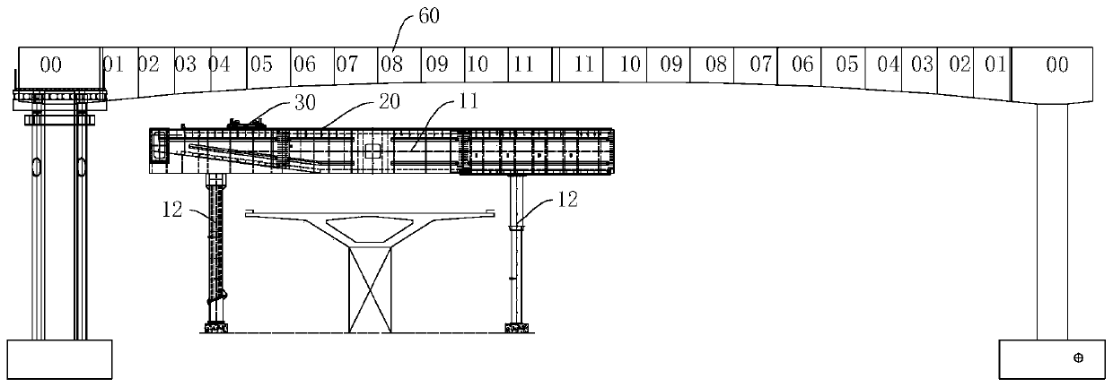
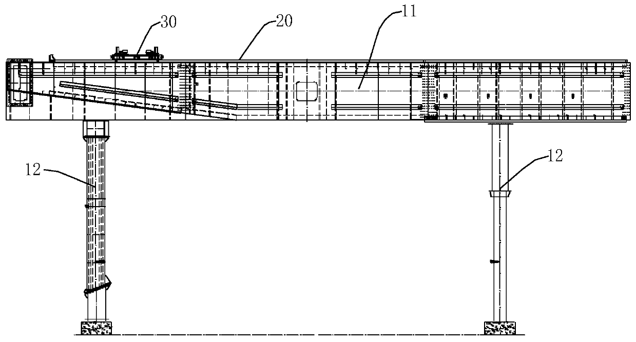
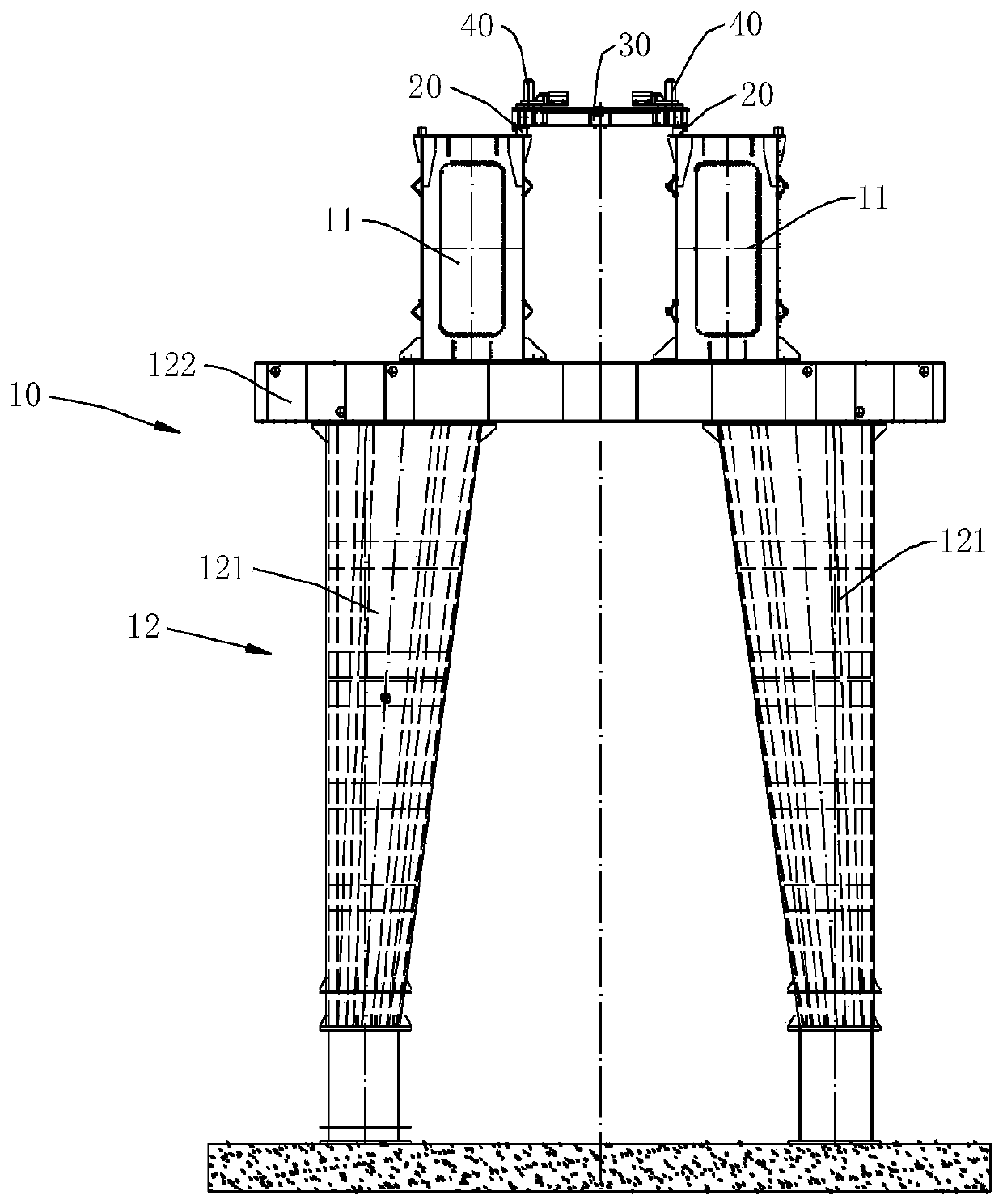
[0037] like Figure 1-Figure 6 As shown, the embodiment of the present invention provides a construction method for segmental beam sliding assembly, including the following steps:

[0038] Step S1, install the sliding bracket 10, such as Figure 2-Figure 4 As shown, the sliding bracket 10 includes a longitudinal beam 11 extending along the axis of the assembling of the segm...


PUM


Abstract

The invention discloses a segmental beam sliding assembly construction method. The construction method comprises the following steps: mounting a sliding bracket, mounting a sliding rail, mounting a beam moving trolley, lifting a beam to the beam moving trolley, transporting the beam by the beam moving trolley, splicing segmental beams, temporarily tensioning, tensioning internal prestressed tendons, repeating the mounting of the next segmental beam, constructing a mid-span closure segment, and dismounting the sliding bracket. According to the invention, the segmental beams are assembled by adopting a sliding assembly method, the segmental beams do not influence the passage or other operations at the lower part of the bracket during sliding assembly, the operating environment with passage requirements or limited topographic conditions can be met, the requirement on segmental beam hoisting equipment is lower by adopting the sliding method, and the cost of the installation equipment is effectively reduced.

Description

technical field [0001] The invention relates to the technical field of prefabricated segment beam installation, in particular to a construction method for segment beam sliding assembly. Background technique [0002] Prefabricated prefabricated segmental beams often intersect with existing separate overpass bridges, roads and other existing lines during on-site installation. Due to the bearing capacity of the original bridge, traffic flow and other reasons, it is necessary to not interrupt the traffic and not affect the existing bridge. In the case of the upper span, the segmental beam is erected. The use of traditional cranes, bridge erecting machines, bridge deck cranes and other equipment cannot be used for erection work due to the impact of the construction space. Among them, the crane cannot meet the lifting capacity within its operating performance range due to the lifting and hoisting capacity, or it needs to be installed with a super-large tonnage crane, and its cost ...

Claims


Application Information

Patent Timeline
IPC IPC(8): E01D21/00
CPCE01D21/00
Inventor 李晓兵尚鹏军王炜徐爽张清夏贾杨宾宋志涛郝迎超张锦辉张龙
Owner CHINA CREC RAILWAY ELECTRIFICATION BUREAU GRP
Learn More