Automobile lock

A car lock and locking technology, which is applied in the field of car locks, can solve the problems of assembling car locks and other problems, and achieve the effect of stable solidification and high structural freedom

Active Publication Date: 2020-05-22
KIEKERT & KOMMANDITGES
View PDF6 Cites 0 Cited by
  • Summary
  • Abstract
  • Description
  • Claims
  • Application Information

AI Technical Summary

Problems solved by technology

In particular, the many metal components that, although serving different functions, make the assembly extremely complex may make the resulting car lock very heavy.

Method used


Image

  • Automobile lock
  • Automobile lock

Examples


Embodiment Construction

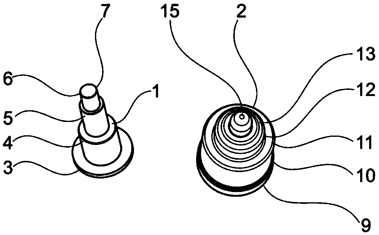
[0031] figure 1 The cylindrical pin 1 and the reinforcement 2 are shown as separate components. The stud is then formed from a metallic material, in particular steel, while the reinforcing element 2 is formed here as a plastic part.

[0032] The cylindrical pin 1 has a set of different diameters, so that in this embodiment the cylindrical pin 1 is formed as a stepped pin, more preferably as a rivetable stepped pin. The first bearing surface 3 serves as a bearing surface against the wall of the lock housing, wherein the cylindrical pin 1 can be inserted into the lock housing and bears against the outer surface of the lock housing with the bearing surface 3 . The other diameter on the cylindrical pin 1 forms a first step 4 on which the reinforcing member 2 can be fitted. The first step thus serves for the positioning of the stiffener 2 on the cylindrical pin 1 . The second step 5 also forms a bearing surface for the reinforcement 2 . The third step 6 of the cylindrical pin 1...


PUM


Abstract

The invention relates to an automobile lock (20). The automobile lock (20) comprises a rotating jack catch and a locking mechanism of at least one catch pawl, wherein the rotating jack catch can be locked at a locked position by the catch pawl; and the locking mechanism further includes a reinforcing part (2), wherein the reinforcing part (2) can be arranged between two parts (17, 18) of a lock housing (8) and a rotation axis of a part mounted in the automobile lock (20) in a swinging mode is formed, and the reinforcing part (2) can be moved between the housing parts (17, 18).

Description

technical field [0001] The invention relates to a motor vehicle lock having a locking mechanism comprising a rotary pawl and at least one pawl, wherein the rotary pawl can be locked in a locking position, in particular a pre-locking position and / or a main locking position by means of the pawl, the The locking mechanism also includes a reinforcement, wherein the reinforcement can be arranged between the two housing parts and forms an axis of rotation for the component that is pivotably mounted in the vehicle lock. Background technique [0002] More and more functions are incorporated into today's motor vehicles, which on the one hand constitute safety functions and on the other hand increase the comfort of the vehicle user. The existing functionality and comfort functions dictate that many components are required to shape the vehicle's functionality. Especially with regard to vehicle locks, today's functionalities such as electric locking, child protection, electric opening ...

Claims


Application Information

Patent Timeline
IPC IPC(8): E05B85/00E05B85/02
CPCE05B85/00E05B85/02E05B2015/1664E05B79/08
Inventor 刘玉会
Owner KIEKERT & KOMMANDITGES
Why Eureka
Try Eureka