Drag chain

A technology of towline and chain plate, which is applied to towline. field, it can solve problems such as prone to failure, heavy drag chain wear, and high cost, and achieve the effect of preventing waist collapse and improving service life

Pending Publication Date: 2020-05-22
深圳市华南天城机床配件有限公司
View PDF0 Cites 2 Cited by
  • Summary
  • Abstract
  • Description
  • Claims
  • Application Information

AI Technical Summary

Problems solved by technology

[0004] 1. For long-distance towlines, the length of the supporting support for towlines is also longer. This kind of supporting support for long-distance towlines is not only expensive, but also difficult to manage in the later stage, and it is not stable. error occured
[0005] 2. The follow-up support mechanism is only suitable for long-distance towlines running at low speeds. When long-distance towlines reciprocate at high speeds, it will cause partial disjoint of the towlines. The dynamic support mechanism wears heavily on the towline, which will seriously affect the operation reliability of the towline and shorten the service life of the towline

Method used


Image

  • Drag chain
  • Drag chain
  • Drag chain

Examples


Embodiment 1

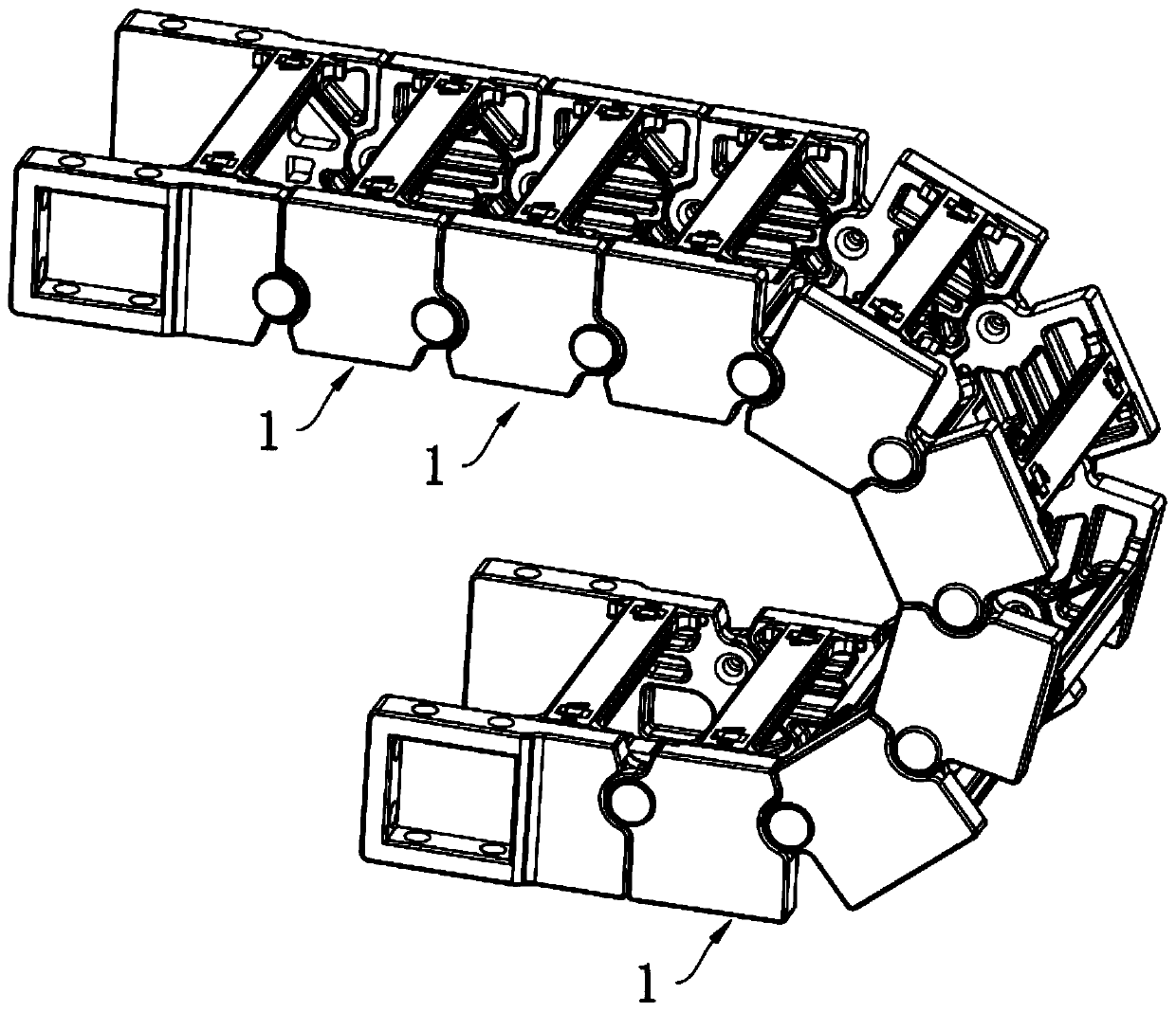
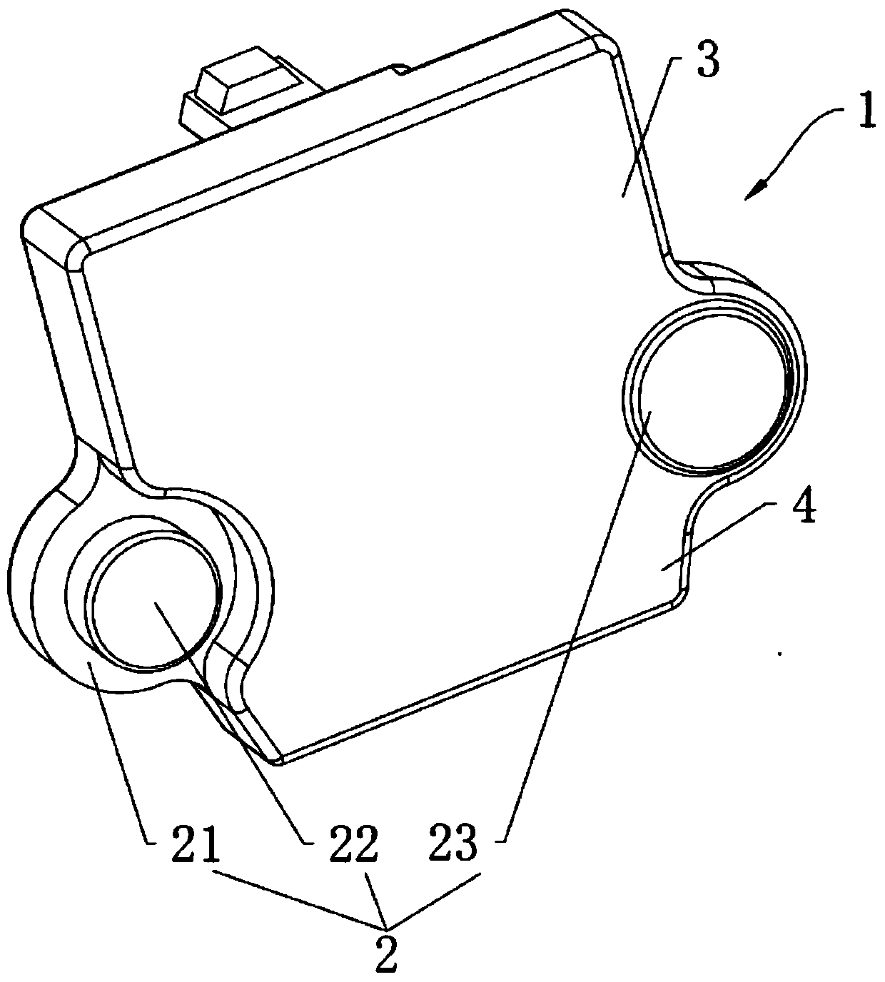
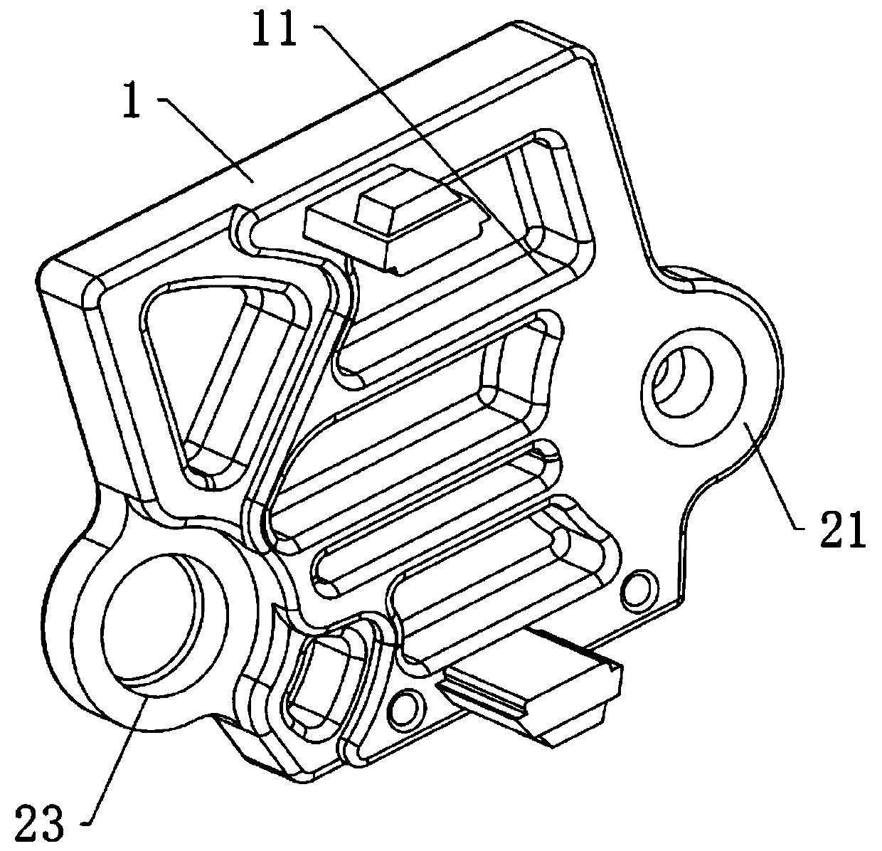
[0035] a drag chain, such as Figure 1-Figure 5 As shown, it includes a plurality of main body chain plates 1 and pins 2 arranged under one side of the main body chain plate 1. The main body chain plate 1 is sequentially hinged at the head and tail through the pins 2, and the axes of the plurality of pins 2 The connection line divides the main chain plate 1 into an upper chain plate 3 and a lower chain plate 4, one side end face of the upper chain plate 3 matches the other side end face of the upper chain plate 3, one side end face of the lower chain plate 4 matches the lower The other end surface of the chain plate 4 is matched, and the plurality of main body chain plates 1 are opened and closed under the support of the pin shaft member 2 .

[0036] In the specific implementation process, during the working process of the towline composed of multiple main chain plates 1, the towline moves horizontally and vertically with the carrier, and the towline itself maintains a level o...

Embodiment 2

[0046] a drag chain, such as Figure 6-Figure 8 As shown, it includes a plurality of main body chain plates 1 and pins 2 arranged under one side of the main body chain plate 1. The main body chain plate 1 is sequentially hinged at the head and tail through the pins 2, and the axes of the plurality of pins 2 The connection line divides the main chain plate 1 into an upper chain plate 3 and a lower chain plate 4, one side end face of the upper chain plate 3 matches the other side end face of the upper chain plate 3, one side end face of the lower chain plate 4 matches the lower The other end surface of the chain plate 4 is matched, and the plurality of main body chain plates 1 are opened and closed under the support of the pin shaft member 2 .

[0047] Wherein, the pin shaft member 2 includes a pin shaft seat 24, a metal sheet 25 and a metal shaft 26. The pin shaft seat 24 is arranged on one side of the main body chain plate 1 and integrally connected with the main body chain pl...


PUM


Abstract

The invention belongs to the technical field of drag chain equipment and discloses a drag chain. The drag chain comprises a plurality of main body chain plates and pin shaft parts; the main body chainplates are sequentially hinged end to end in a limitation manner by virtue of the pin shaft parts; the main body chain plates are divided into upper chain plates and lower chain plates by the linkedline of the axes of the plurality of pin shaft parts; the end face of one side of each upper chain plate is matched with the end face of the other side of the corresponding upper chain plate; the endface of one side of each lower chain plate is matched with the end face of the other side of the corresponding lower chain plate; the plurality of main chain plates are supported by virtue of lever supporting of the pin shaft parts so that the lower chain plates are connected in a leaning manner and the upper chain plates are opened to transform the load force born by the drag chain into longitudinal tensile force of the lower chain plates and the longitudinal jacking force of the upper chain plates, thereby increasing the strength and the bearing capacity of the drag chain and effectively preventing deformation and waist collapse of the drag chain.

Description

technical field [0001] The invention belongs to the technical field of drag chain equipment, and in particular relates to a drag chain. Background technique [0002] At present, the drag chain has been widely used in many fields such as CNC machine tools, stone machinery, glass machinery, door and window machinery, injection molding machines, manipulators, lifting and transportation equipment, automated warehouses, etc. The water pipes play the role of traction and protection, and at the same time make the whole machine look more beautiful. The towlines in the prior art are mostly connected by several main chain plates. When the towline is in use, the towline can be divided into three parts according to the state of motion: the lower section of the towline, the steering ring section and the upper section of the towline. The existing drag chains have a small suspension bearing capacity. When the length of the drag chain is longer, the drag chain will bend to varying degrees ...

Claims


Application Information

Patent Timeline
Patent Type & Authority Applications(China)
IPC IPC(8): F16G13/16F16G15/12
CPCF16G13/16F16G15/12
Inventor 王园园
Owner 深圳市华南天城机床配件有限公司
Why Eureka
Try Eureka