A device for preventing temporary cables from mopping the ground in construction projects

A temporary cable and construction engineering technology, applied in the direction of electrical components, etc., can solve problems such as mopping the floor, complicated states, and cables falling into the ground

Active Publication Date: 2021-03-16
邱凤玲
View PDF10 Cites 0 Cited by
  • Summary
  • Abstract
  • Description
  • Claims
  • Application Information

AI Technical Summary

Problems solved by technology

[0004] In order to solve the above-mentioned technical problems, the present invention provides a device for preventing temporary cables from dragging the ground in construction projects, so as to solve the problem that the remaining wire harness will be damaged if there is no auxiliary supporting device during the erection of existing multi-strand core cables. The phenomenon of mopping the ground occurs, that is, the bending section of the remaining wire harness after erection will fall to the ground due to gravity, causing the cables to fall to the ground, which is very easy to cause accidents. The existing solution is to use the bracket to place the remaining material cables The section is supported upwards and separated from the ground. In order to improve its stability, the support frame used at this time often needs to be inserted into the ground for firm fixation, which makes it difficult to use it flexibly again during cable maintenance, especially for redundant cable sections. It cannot be well stored on the top of the bracket, and its state is intricate and unsightly

Method used


Image

  • A device for preventing temporary cables from mopping the ground in construction projects
  • A device for preventing temporary cables from mopping the ground in construction projects
  • A device for preventing temporary cables from mopping the ground in construction projects

Examples


Embodiment

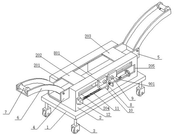
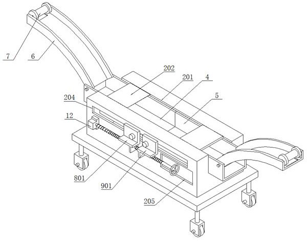
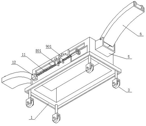
[0030] as attached figure 1 to attach Figure 8 Shown:

[0031] The present invention provides a device for preventing temporary cables from mopping the ground in construction projects, including a base 1; the base 1 is a hollow rectangular seat structure, and a rectangular cavity seat 2 is vertically welded on its top surface, such as image 3 As shown, the overall cavity base is a shell cavity structure, which is light in structure and easy to use; the cavity base 2 has an inner channel 201 in the shape of a rectangular opening from left to right, and through this inner channel 201, the left and right sides of the inner cavity of the cavity base 2 The first wire support frame 4 and the second wire support frame 5 are slidingly fitted on both sides respectively; the top ends of the first wire support frame 4 and the second wire support frame 5 are respectively fixed with bolts for supporting wires in a figure-eight pattern. The left and right wire support seats 6, both of t...


PUM


Abstract

The invention provides a device for preventing a constructional engineering temporary cable from mopping the ground. The device comprises a base, the base is of a hollow rectangular base structure, and a rectangular cavity base is perpendicularly welded to the top face of the base. The cavity base is provided with a rectangular through-opening type inner channel from left to right, and a first wire supporting frame and a second wire supporting frame are arranged on the left side and the right side of an inner cavity of the cavity base in a sliding fit mode respectively through the inner channel. Wire supporting seats are fixed at the top ends of the first wire supporting frame and the second wire supporting frame through bolts respectively, and a first top sealing plate and a second top sealing plate are respectively welded in an inner channel formed in the top end of the cavity seat in a bilateral symmetry manner. According to the left-right adjustable arc-shaped frame of the device,left-right guiding and moving can be conducted on an allowance wire harness, the wire harness arranged in the left-right direction can be erected in a splayed mode according to the actual wiring and erecting process, the width supporting range can be adjusted, flexibility and practicability are further improved, and the functional structure is superior to that of a simple cable supporting frame.

Description

technical field [0001] The invention belongs to the technical field of cable erection auxiliary devices, and more specifically relates to a device for preventing temporary cables from dragging the ground in construction projects. Background technique [0002] The cable is usually a rope-like cable twisted by several or groups of wires [at least two in each group]. Each group of wires is insulated from each other and is often twisted around a center. Insulating covering. Most of them are erected in the air or installed underground or underwater for telecommunications or power transmission. An insulated wire consisting of one or more mutually insulated conductive cores placed in a sealed sheath. A protective covering can be added to the outside for transmission, distribution of electrical energy or transmission of electrical signals. The difference between it and ordinary wires is mainly that the cable size is larger and the structure is more complicated. [0003] During t...

Claims


Application Information

Patent Timeline
Patent Type & Authority Patents(China)
IPC IPC(8): H02G3/04
CPCH02G3/045
Inventor 邱凤玲
Owner 邱凤玲
Why Eureka
Try Eureka