Universal testing machine

A technology of universal testing machine and test head, applied in the field of universal testing machine, can solve problems such as trouble

Pending Publication Date: 2020-05-26
ベロテクノロジーズドンタイカンパニーリミテッド
View PDF0 Cites 2 Cited by
  • Summary
  • Abstract
  • Description
  • Claims
  • Application Information

AI Technical Summary

Problems solved by technology

[0004] However, the traditional universal testing machine does not have the function of moving the traditional lifting hydraulic cylinder 202 back and forth or left and right. Therefore, when the component under te

Method used


Image

  • Universal testing machine
  • Universal testing machine
  • Universal testing machine

Examples


Embodiment Construction

[0029] The present invention will be described in further detail below in conjunction with the accompanying drawings.

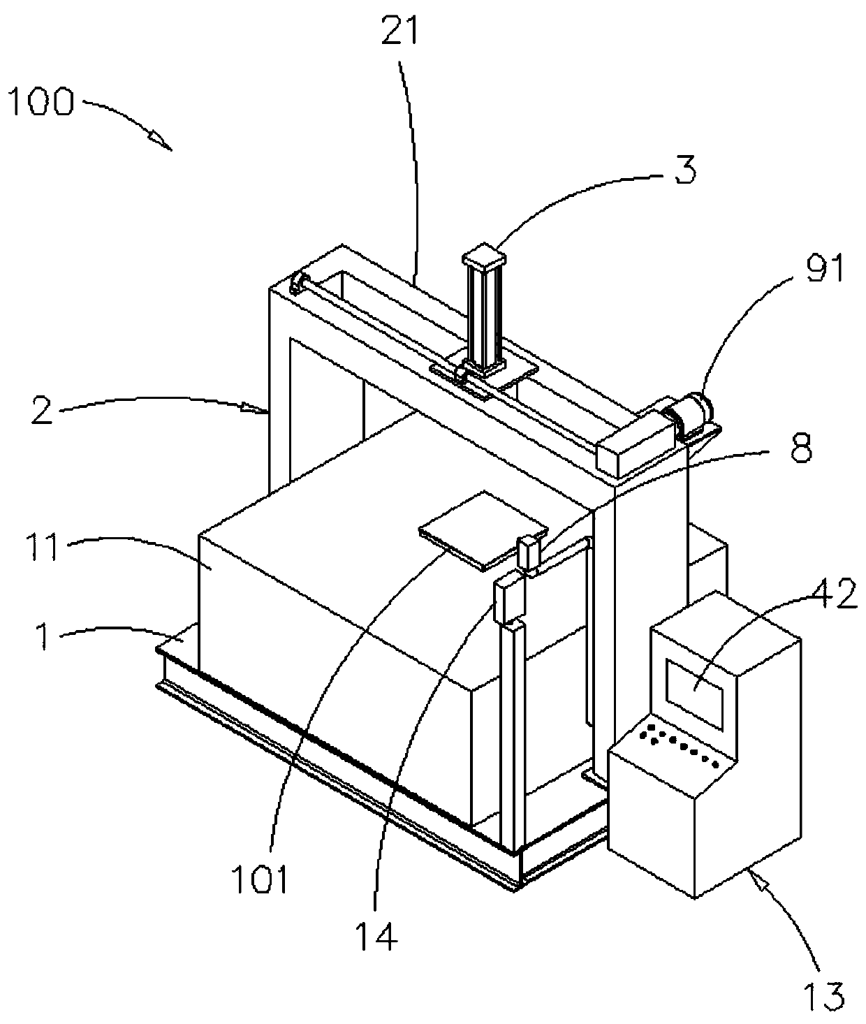
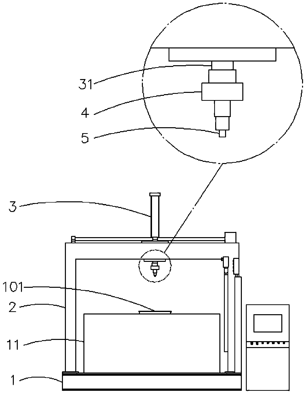
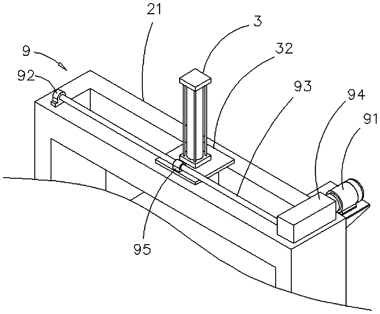
[0030] Such as Figure 1-3 and Figure 6 As shown, a kind of universal testing machine 100 of the present invention comprises: a test platform 1, is used to place a tested component 101; And a support 2, is located on the test platform 1, and the top of support is provided with a track 21; And a The lifting hydraulic cylinder 3 is arranged on the rail 21 to move left and right, and has a downwardly telescopic lifting hydraulic axis 31; and a load cell 4, which is arranged at the bottom end of the lifting hydraulic axis 31; and a test head 5 , located at the bottom of the load cell 4, used to contact the tested component 101; the load cell 4 is used to test the force between the test head 5 and the tested component 101 to obtain a test value; and a hydraulic machine 6, connected to the lifting hydraulic cylinder 3; and a first switch 7 connected to the hydra...


PUM


Abstract

The invention discloses a universal testing machine, which mainly comprises a testing platform, a bracket, a lifting hydraulic cylinder, a loading element, a testing head, and a left-right moving mechanism, wherein the testing platform is used for placing a tested assembly; the bracket is arranged on the testing platform, and a track is arranged at the top of the bracket; the lifting hydraulic cylinder is arranged on the rail in a left-right moving mode and is provided with a lifting hydraulic axis capable of stretching downwards; the loading element is arranged at the bottom end of the lifting hydraulic axis; the testing head is arranged at the bottom of the loading element and is used for contacting with the tested assembly; the loading element is used for testing the force between the testing head and the tested assembly to obtain a test value; and the left-right moving mechanism is used for driving the lifting hydraulic cylinder to move left and right along the rail. Through the structure, the compressive strength and the tensile strength of the tested assembly can be conveniently tested from different positions under the condition that the tested assembly is fixed.

Description

technical field [0001] The invention relates to a device capable of testing the compressive strength and tensile strength of various tested components, in particular to a universal testing machine. Background technique [0002] When constructing projects such as raised floors, there are many components that need to reach a predetermined strength before they can be used. For example, the floor unit of the raised floor not only needs to have a predetermined compressive strength, but also needs to test the deformation of the floor unit under the predetermined pressure, while the foot frame of the raised floor needs to have a predetermined tensile strength. Therefore, it is urgently needed in the industry to develop a testing machine capable of testing various tested components such as floor units and tripods. [0003] Such as Figure 10 As shown, the traditional universal testing machine 200 generally has a traditional test platform 201, a traditional lifting hydraulic cylinde...

Claims


Application Information

Patent Timeline
IPC IPC(8): G01N3/10G01N3/12G01N3/02
CPCG01N3/02G01N3/10G01N3/12G01N2203/0017G01N2203/0019G01N2203/0048
Inventor 黄建德
Owner ベロテクノロジーズドンタイカンパニーリミテッド
Why Eureka
Try Eureka