
Physical evidence investigation equipment

A technology of physical evidence and equipment, applied in the field of physical evidence investigation equipment, can solve the problems of on-site pollution and achieve the effect of reducing the polluted area

Pending Publication Date: 2020-05-26
杭州衡利电子技术有限公司
View PDF0 Cites 4 Cited by
  • Summary
  • Abstract
  • Description
  • Claims
  • Application Information

AI Technical Summary

Problems solved by technology

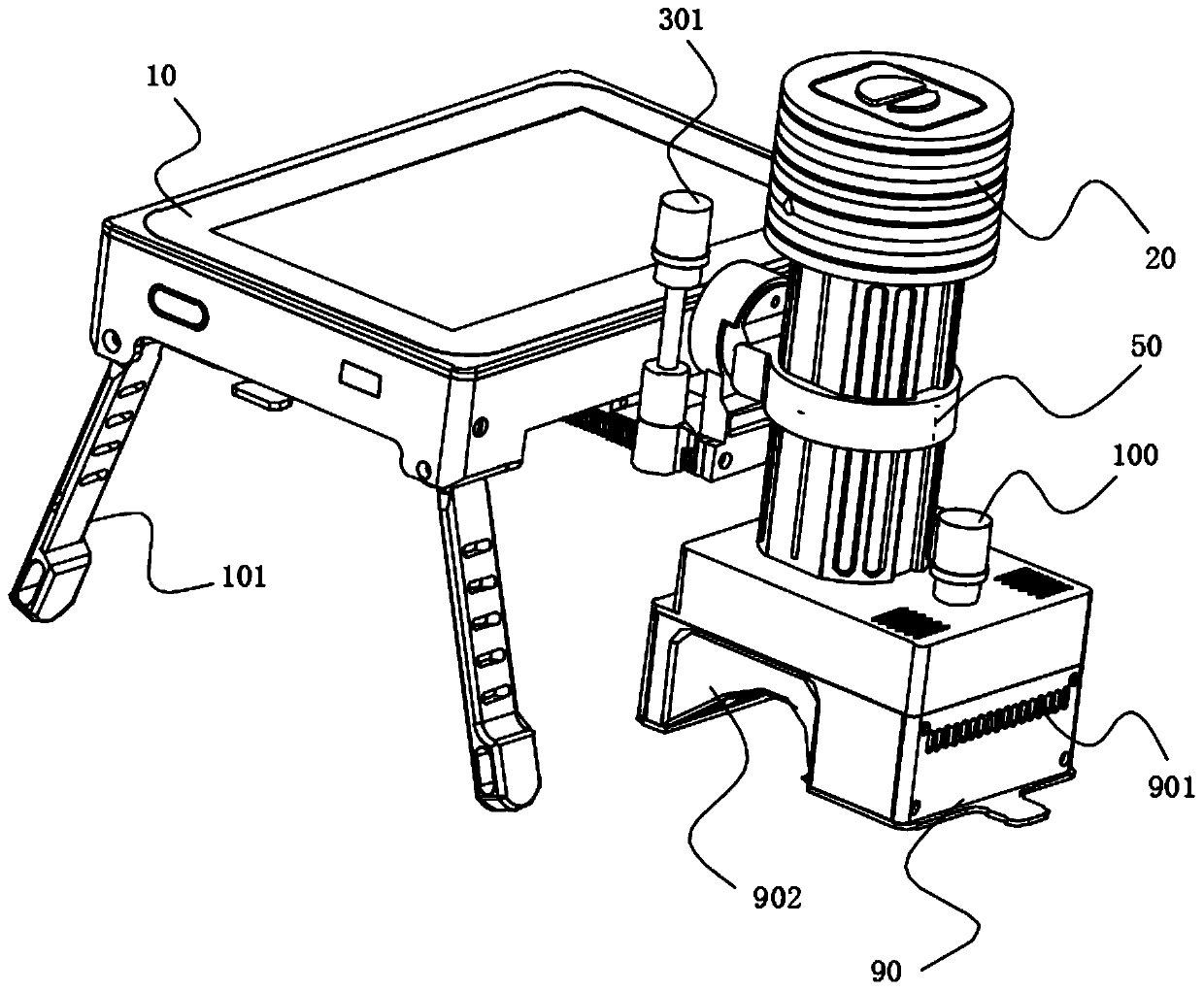
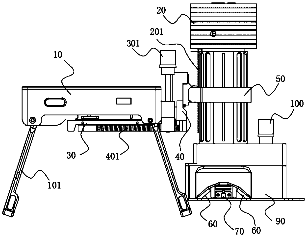
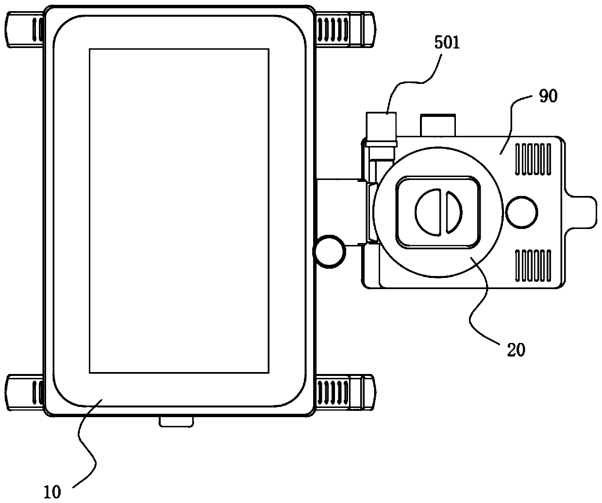
[0005] The object of the present invention is to provide a physical evidence survey equipment to alleviate the technical problem that the physical evidence survey equipment in the prior art is likely to cause a large area of ​​pollution to the site

Method used


Image

  • Physical evidence investigation equipment
  • Physical evidence investigation equipment
  • Physical evidence investigation equipment

Examples


Embodiment Construction

[0060] The technical solutions of the present invention will be clearly and completely described below in conjunction with the accompanying drawings. Apparently, the described embodiments are some of the embodiments of the present invention, but not all of them. Based on the embodiments of the present invention, all other embodiments obtained by persons of ordinary skill in the art without making creative efforts belong to the protection scope of the present invention.

[0061] In the description of the present invention, it should be noted that the orientation or positional relationship indicated by the terms "inner", "outer" and the like are based on the orientation or positional relationship shown in the drawings, and are only for the convenience of describing the present invention and simplifying the description. It is not intended to indicate or imply that the referred device or element must have a particular orientation, be constructed in a particular orientation, and ope...


PUM


Abstract

The invention relates to the technical field of investigation equipment, in particular to physical evidence investigation equipment, which comprises a base, a microscope and a position adjusting mechanism. The base can be fixed on the surface of an object, the base and the microscope are both connected with the position adjusting mechanism, the position adjusting mechanism is used for adjusting the relative position of the microscope and the base, and the microscope can move relative to the base in the direction parallel to the fixed surface, making contact with the surface of the object, of the base. According to the physical evidence investigation equipment provided by the invention, the pollution area to the site can be reduced.

Description

technical field [0001] The invention relates to the technical field of investigation equipment, in particular to physical evidence investigation equipment. Background technique [0002] Physical evidence investigation equipment can bring great help to the detection of criminal cases, and is widely used in the investigation of various physical evidence (such as: human body shedding dander, sweat, blood, saliva spots, semen spots, etc.) at the scene of a case. [0003] There are some physical evidence investigation equipment equipped with a microscope. When in use, the microscope is fixed (directly or indirectly) to the surface of the object to ensure that the lens of the microscope can stabilize the image. After the area that can be observed, the fixed position needs to be replaced, and the area that can be observed by the microscope each time (in millimeters) is small, and the area (in meters) that needs to be surveyed on site is large, forming a huge proportion, so replace ...

Claims


Application Information

Patent Timeline
Patent Type & Authority Applications(China)
IPC IPC(8): G02B21/24G02B21/26
CPCG02B21/24G02B21/26
Inventor 宋志宏
Owner 杭州衡利电子技术有限公司
Learn More