Magnetic synchronizer and transmission

A synchronizer and transmission technology, applied in the transmission field, can solve the problems of noise generated during use and short service life of the synchronizer, and achieve the effects of improving the shifting speed, low cost and long service life.

Pending Publication Date: 2020-05-29
HARBIN INST OF TECH AT WEIHAI
View PDF0 Cites 1 Cited by
  • Summary
  • Abstract
  • Description
  • Claims
  • Application Information

AI Technical Summary

Problems solved by technology

[0003] The purpose of the present invention is to provide a magnetic synchronizer, aiming to solve the technical problems that the existing synchronizer has a short service life and generates noise during use

Method used


Image

  • Magnetic synchronizer and transmission
  • Magnetic synchronizer and transmission
  • Magnetic synchronizer and transmission

Examples


Embodiment Construction

[0027] In order to make the technical problems, technical solutions and beneficial effects to be solved by the present invention clearer, the present invention will be further described in detail below in conjunction with the accompanying drawings and embodiments. It should be understood that the specific embodiments described here are only used to explain the present invention, not to limit the present invention.

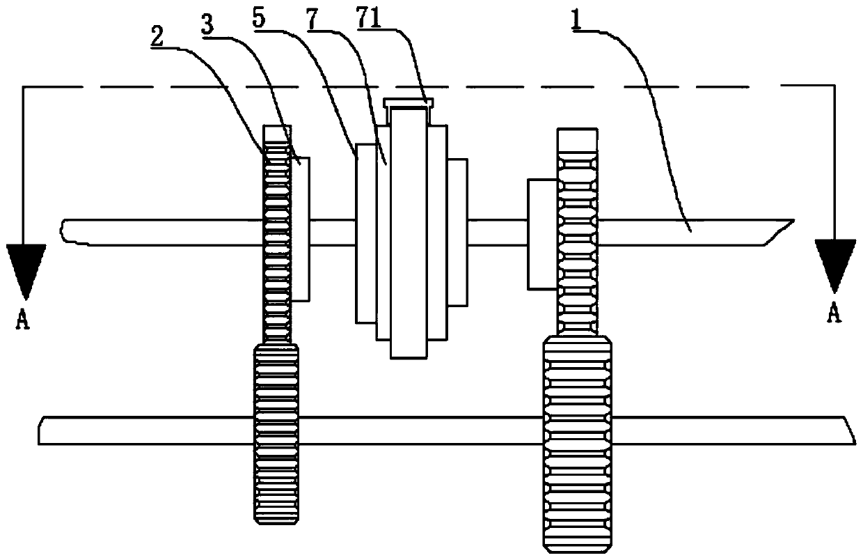
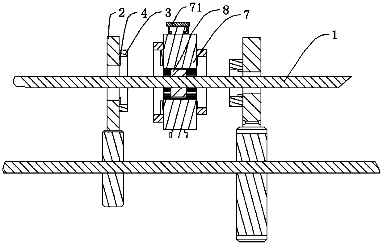
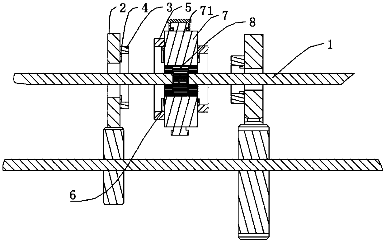
[0028] Please also refer to Figure 1 to Figure 7 , a magnetic synchronizer provided by the present invention is now described. The magnetic synchronizer includes a gear hub 8, an adapter sleeve 7, a first magnetic member 3 and a second magnetic member 5, the gear hub 8 is used for coaxial connection with the output shaft 1; the adapter sleeve 7 is coaxially sleeved on the On the gear hub 8, it is used to freely slide along the axial direction of the gear hub 8 when driven by an external force; the first magnetic part 3 is provided with a plurality of N poles and ...


PUM


Abstract

The invention provides a magnetic synchronizer and a transmission. The magnetic synchronizer comprises a gear hub, a joint sleeve, a first magnetic piece and a second magnetic piece, wherein the gearhub is used for being coaxially connected with an output shaft; the joint sleeve is coaxially arranged on the gear hub in a sleeving mode and used for freely sliding in the axial direction of the gearhub when being driven by external force; a plurality of N poles and S poles which are arranged in a staggered manner are arranged on the first magnetic piece, and the first magnetic piece is used forbeing fixedly connected with an idle gear which idles on the output shaft; the second magnetic piece is fixedly connected with the joint sleeve, and a plurality of N poles and S poles which are arranged in a staggered manner are arranged on the second magnetic piece; and when the magnetic synchronizer is used for gear shifting operation, a magnetic field generated by the first magnetic piece is matched to drive the joint sleeve and the idle gear to rotate synchronously. The magnetic synchronizer provided by the invention has no noise, and the structure of the synchronizer cannot be abraded; and friction is not generated in the gear shifting process, and the gear shifting speed is improved. The magnetic synchronizer also has the characteristics of low cost, convenient manufacture and longservice life.

Description

technical field [0001] The invention belongs to the technical field of transmission, and more specifically relates to a magnetic synchronizer and a speed changer. Background technique [0002] Existing synchronizers for automobile gearboxes include normal pressure type, inertia type, and self-energizing type. At present, the inertial synchronizer is the most widely used. The inertial synchronizer is mainly composed of an adapter sleeve, a synchronous lock ring, etc. It is characterized by relying on friction to achieve synchronization, and its disadvantage is that noise will be generated during the friction process; synchronizer The inner and outer tapered surfaces of the synchronizer will be continuously worn during the working process, which will shorten the service life of the synchronizer. Contents of the invention [0003] The purpose of the present invention is to provide a magnetic synchronizer, aiming to solve the technical problems of short service life of existi...

Claims


Application Information

Patent Timeline
Patent Type & Authority Applications(China)
IPC IPC(8): F16D23/02F16D27/14
CPCF16D23/025F16D27/14
Inventor 王杰雄刘涛
Owner HARBIN INST OF TECH AT WEIHAI
Why Eureka
Try Eureka