Microscope optical adaptation device

A technology for adapting a device and a microscope, applied in the field of medical devices, can solve problems such as inconvenient use of video, and achieve the effects of simple structure, convenient adjustment and good operation effect.

Active Publication Date: 2020-05-29
ZUMAX MEDICAL
View PDF6 Cites 0 Cited by
  • Summary
  • Abstract
  • Description
  • Claims
  • Application Information

AI Technical Summary

Problems solved by technology

[0004] The photosensitive unit of digital camera equipment is rectangular, and the output signal sequence is fixed, that is, it has different directions of up, down, left, and right. However, images captured by digital camera equipment usually need to be uploaded to a computer or network for viewing, saving, editing, etc., and the direction is wrong. The video is inconvenient to use, such as Figure 2a , 2b 、As shown in 2c, it needs to be adjusted by video software (it can only be flipped in multiples of 90 degrees)

Method used


Image

  • Microscope optical adaptation device
  • Microscope optical adaptation device
  • Microscope optical adaptation device

Examples


Embodiment 1

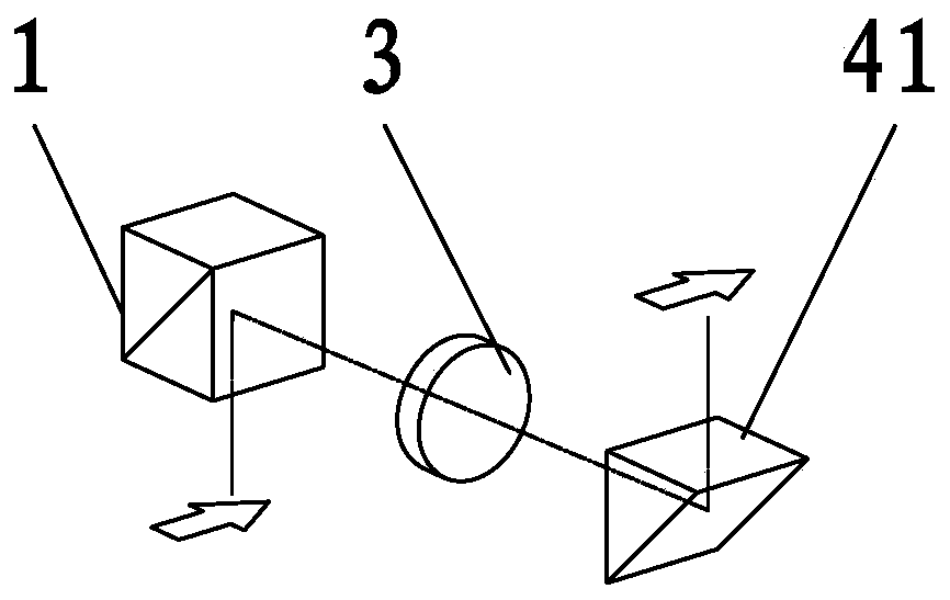
[0036] Such as image 3 Shown: a microscope optical adaptation device, including a Dove prism 20 , a lens group 3 , and a pentaprism 40 sequentially arranged on the beam-splitting optical path of the beam-splitting prism 1 of the beam-splitting unit A. Rotating the dove prism 20 alone can adjust the direction of the optical image formed on the photosensitive units of the digital camera equipment C1, C2, and C3.

Embodiment 2

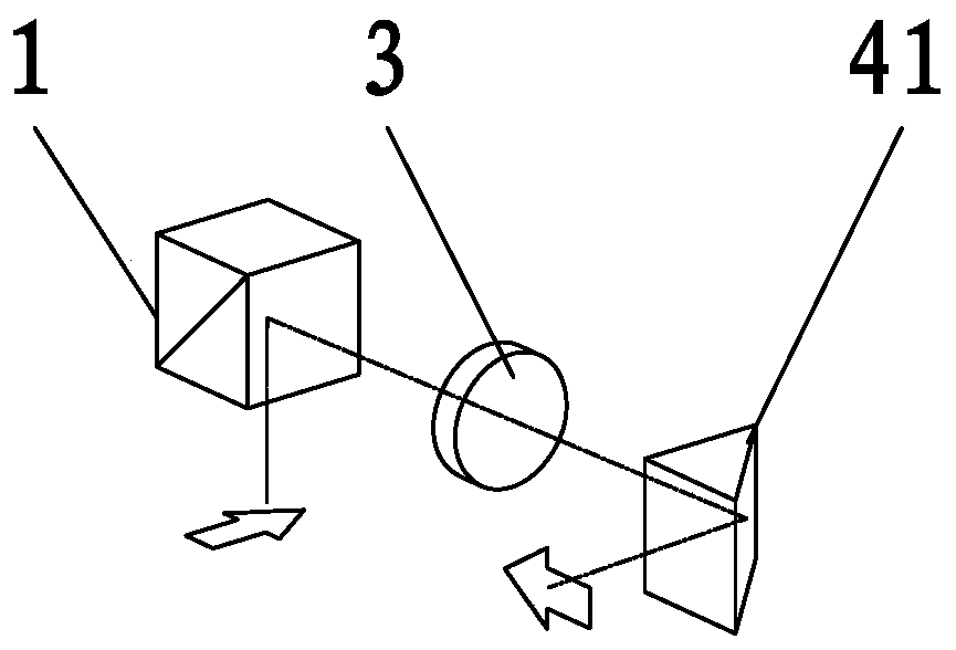
[0038] Such as Figure 4 Shown: a microscope optical adaptation device, including a Dovey roof prism 21, a lens group 3, and a right-angle prism 41 sequentially arranged on the beam-splitting optical path of the beam-splitting prism 1 of the beam-splitting unit A. Rotating the Dove roof prism 21 alone can adjust the direction of the optical image formed on the photosensitive units of the digital camera equipment C1, C2, and C3.

Embodiment 3

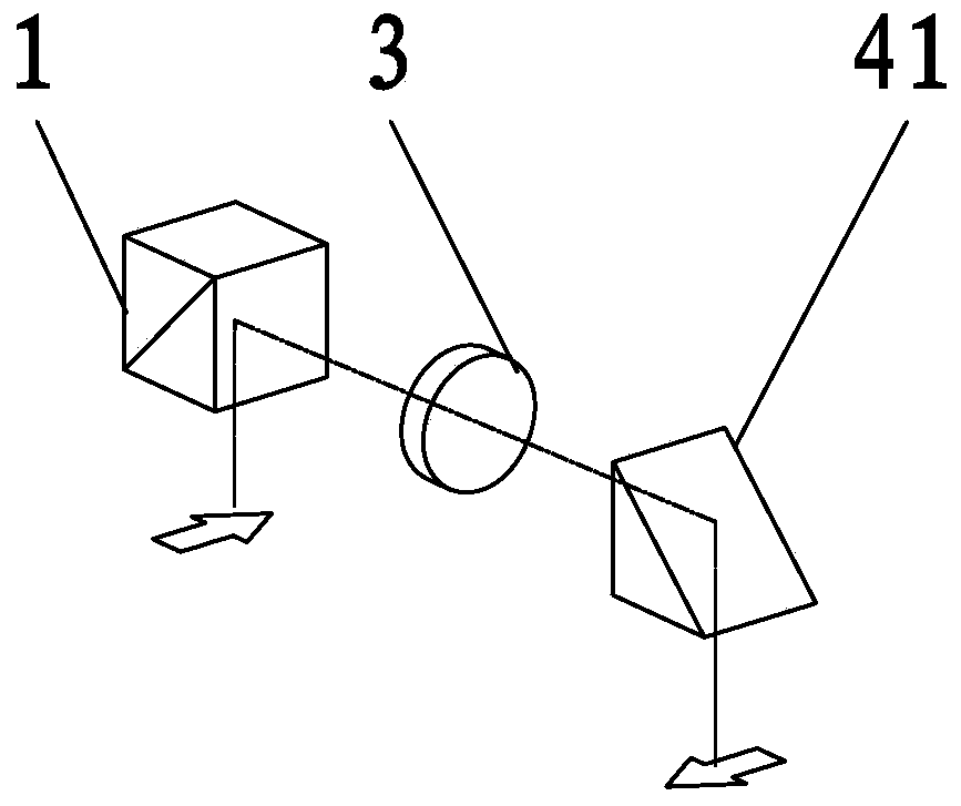
[0040] Such as Figure 5 Shown: a microscope optical adaptation device, including a Dove prism 20 , a lens group 3 , and two right-angle prisms 41 arranged sequentially on the beam-splitting optical path of the beam-splitting prism 1 of the beam-splitting unit A. Using two right-angle prisms can be adjusted in two directions, and similarly can continue to increase reflections to become multi-dimensional adjustments. The two right-angle prisms can be adjusted in two directions, which means that the first direct prism can rotate and adjust the angle in one direction dimension, and the second right-angle prism can also rotate and adjust the angle in the other direction dimension. Rotating the dove prism 20 alone can adjust the direction of the optical image formed on the photosensitive units of the digital camera equipment C1, C2, and C3.


PUM


Abstract

The invention relates to a microscope optical adaptation device. The device is connected between a light splitting element of a microscope and digital camera shooting equipment. The microscope comprises an operation microscope and a slit lamp microscope; the digital camera shooting equipment comprises a mobile phone with an image capturing function, a tablet personal computer, a camera and a videocamera. The optical adaptation device comprises a lens group located on an optical path. The optical adaptation device further comprises an optical image rotating component used for adjusting the direction of an optical image imaged on a photosensitive unit of the digital camera shooting equipment, the optical image rotating component comprises an optical image rotating lens set located on the optical path, and the optical image rotating lens set can independently rotate around the optical axis. Or the optical image rotating lens set is fixedly arranged. The direction of the optical image onthe photosensitive unit in the digital camera shooting equipment can be adjusted in real time, the satisfactory direction can be obtained no matter where the device is located, the structure is simple, the adjustment is convenient, and the user experience operation effect is good.

Description

[0001] The present invention is an application number: 201710238871.0, the application date is: April 13, 2017, and the name of the invention is: a divisional application of a Chinese invention patent application for a microscope optical adapter device technical field [0002] The invention relates to the field of medical instruments, in particular to a microscope optical adaptation device. Background technique [0003] The existing microscope optical adapter device B is used to connect the light splitting unit A of the microscope with the digital camera equipment C1, C2, C3, see Figure 2a , 2b , 2c. When the microscope optical adapter device B is connected to the spectroscopic device A, it can be rotated by selecting the bayonet direction, usually 90 degrees per step (in order to adjust the direction of digital camera equipment C1, C2, C3, such as digital camera equipment C1, C2 , C3 facing upwards, forwards, downwards or backwards), and changing the angle requires disass...

Claims


Application Information

Patent Timeline
Patent Type & Authority Applications(China)
IPC IPC(8): G02B21/36
CPCG02B21/361
Inventor 李剑月杜雷杨晓光
Owner ZUMAX MEDICAL
Why Eureka
Try Eureka