[0035] In order to make the objectives, technical solutions and advantages of the present invention clearer, the embodiments of the present invention will be described in detail below in conjunction with the accompanying drawings. It should be noted that the embodiments in the application and the features in the embodiments can be combined with each other arbitrarily if there is no conflict.
[0036] The steps shown in the flowchart of the drawings can be executed in a computer system such as a set of computer-executable instructions. Also, although a logical sequence is shown in the flowchart, in some cases, the steps shown or described may be performed in a different order than here.
[0037] Unless otherwise defined, the technical or scientific terms used in the present disclosure shall have the usual meanings understood by those with ordinary skills in the field to which the present invention belongs. The "first", "second" and similar words used in the present disclosure do not indicate any order, quantity, or importance, but are only used to distinguish different components. "Include" or "include" and other similar words mean that the element or item appearing before the word covers the element or item listed after the word and its equivalents, but does not exclude other elements or items. Similar words such as "connected" or "connected" are not limited to physical or mechanical connections, but may include electrical connections, whether direct or indirect. "Up", "Down", "Left", "Right", etc. are only used to indicate the relative position relationship. When the absolute position of the described object changes, the relative position relationship may also change accordingly.
[0038] When a large screen uses the center point as the benchmark for Gamma tuning (gamma tuning), the center point meets the target gamma curve (such as the Gamma2.2 curve), because of the large size and the problem of brightness uniformity. The position around the center point, It cannot meet the standard Gamma 2.2 curve. Therefore, it is necessary to make improvements.
[0039] In the embodiment of the present application, after gamma debugging is performed on the reference area, the remaining areas are compensated, thereby improving the uniformity of the screen.
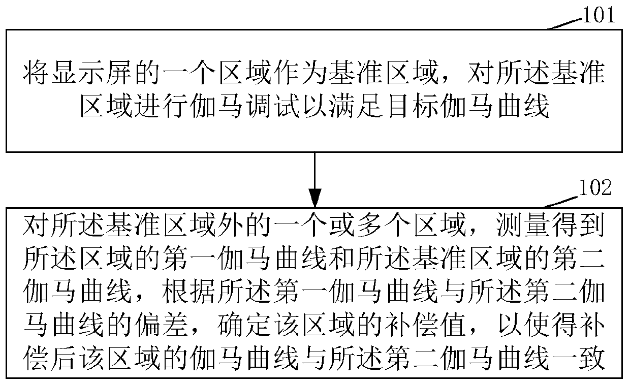
[0040] Such as figure 1 As shown, an embodiment of the present application provides a gamma compensation method, including:
[0041] Step 101: Use an area of the display screen as a reference area, and perform gamma adjustment on the reference area to meet the target gamma curve;
[0042] Step 102: For one or more areas outside the reference area, measure the first gamma curve of the area and the second gamma curve of the reference area, according to the first gamma curve and the The deviation of the second gamma curve determines the compensation value of the area, so that the gamma curve of the area after compensation is consistent with the second gamma curve.
[0043] The solution provided in this embodiment compensates for the area outside the reference area, so that its gamma curve is consistent with the gamma curve of the reference area, which improves the uniformity of the display screen. In addition, compared to the solution of performing gamma debugging on each area, the gamma curve can be compensated in this embodiment, which is more convenient to implement.
[0044] In an exemplary embodiment, the reference area is an area including the center point of the display screen. In other embodiments, the reference area may also be an area that does not include the center point.
[0045] In an exemplary embodiment, the display screen is evenly divided into 9 areas; wherein, the reference area is an area including the center point of the display screen. Such as figure 2 As shown, the display screen is divided into 9 areas, and area A is taken as the reference area. In other embodiments, it may be divided into more or less regions, and the size of each region may also be different, which may be divided according to needs.
[0046] The target gamma curve includes an R (red) component gamma curve, a G (green) component gamma curve, and a B (blue) component gamma curve. In the embodiments of the present application, it is only called the target gamma curve in general, and when performing gamma debugging, it needs to be debugged separately.
[0047] In an exemplary embodiment, in step 101, performing gamma debugging on the reference area to meet the target gamma curve includes: adjusting the control voltage according to the target brightness value corresponding to the gray scale of the bound point on the target gamma curve , Make the brightness value of the gray scale of the reference area at the binding point reach the target brightness value, and record the corresponding control voltage, that is, the gamma voltage (recorded by the gamma register), including the R component gamma voltage and G component gamma Voltage and B component gamma voltage. After obtaining the gamma voltage of the binding point gray scale, the gamma voltage of other gray scale binding points is obtained by interpolation, and the gamma debugging is completed. Wherein, the target gamma curve may correspond to a specified gamma value, for example, it may be 2, 2.1, 2.2, 2.3, 3, etc., which is not limited in this application. When the gamma value is 2.2, the human eye recognizes that the progression of the brightness of each gray scale is equidistant. Therefore, in an exemplary embodiment, the gamma value of the target gamma curve may be 2.2, that is, The target gamma curve includes R component 2.2 gamma curve, G component 2.2 gamma curve, and B component 2.2 gamma curve. It should be noted that the above gamma debugging method is only an example, and other gamma debugging methods can be used as needed.
[0048] The display screen is divided into multiple areas. For the area of the reference area, each area can be compensated, or only part of the area can be compensated, for example, measuring the gamma curve of each area and the gamma of the reference area. The curves are compared, and when the preset conditions are met (for example, the deviation reaches the preset degree), compensation is performed. If the deviation is small, no compensation is performed. Of course, it is also possible to directly perform the compensation operation in step 102 without making a judgment.
[0049] In the step 102, the method of measuring the gamma curve is to measure the brightness value under each gray scale to obtain the gamma curve representing the relationship between the brightness value and the gray scale.
[0050] In another embodiment, the second gamma curve can also directly use the target gamma curve.
[0051] In an exemplary embodiment, the determining the compensation value of the region according to the deviation of the first gamma curve and the second gamma curve includes:
[0052] Convert the first gamma curve of the region into a first linear curve, convert the second gamma curve into a second linear curve, and determine according to the deviation of the first linear curve and the second linear curve The compensation value of this area. In other embodiments, the conversion may not be performed directly, and the compensation may be directly performed according to the deviation between the first gamma curve and the second gamma curve. Among them, the compensation value is the compensation value for the gamma voltage.
[0053] In an exemplary embodiment, converting the first gamma curve into a first linear curve, and converting the second gamma curve into a second linear curve includes: taking a natural pair of the first gamma curve The first linear curve is obtained by counting, and the second gamma curve is taken as a natural logarithm to obtain the second linear curve.
[0054] The first gamma curve and the second gamma curve are the relationship between brightness lv and gray scale GrayN-; the first gamma curve satisfies lv=maximum brightness*[(GrayN-0)/(255-0 )]^a1, a1 is the gamma value of the first gamma curve; the second gamma curve satisfies lv=maximum brightness*[(GrayN-0)/(255-0)]^a2, a2 is the second The gamma value of the gamma curve;
[0055] Take the natural logarithm of the first gamma curve to obtain the first linear curve, which satisfies Y=ln(lv)=ln(maximum brightness*[(GrayN-0)/(255-0)]^a1), Taking ln(lv) as the vertical axis and ln(GrayN) as the horizontal axis, the first linear curve is obtained. The second linear curve is similar and will not be repeated. In other embodiments, other methods may be used to perform linearization, which is not limited in this application.
[0056] Among them, the calculation deviation refers to: calculating the difference between the Y value of the first linear curve and the second linear curve of the same gray scale, and obtaining the compensation value according to the difference, so that the brightness value of the area under the same gray scale after compensation is compared with the reference area The brightness values are consistent (that is, the gamma curve is consistent), which improves the brightness uniformity of the display screen. If all areas are compensated, the brightness uniformity of the entire display screen is improved. The compensation value can be recorded in the register. At this time, different gamma voltages are applied to this area and the reference area.
[0057] In an exemplary embodiment, the determining the compensation value of the area according to the deviation of the first linear curve and the second linear curve includes:
[0058] Select multiple gray levels, determine the compensation value of the multiple gray levels in the area according to the deviation of the first linear curve and the second linear curve in the multiple gray levels, and determine the compensation value of the multiple gray levels according to the compensation value of the multiple gray levels , Interpolate to obtain the compensation value of the remaining gray levels in the area. That is, multiple gray scales can be selected to calculate deviations and compensated, and the compensation values of other gray scales are obtained by interpolation of the compensation values of the multiple gray scales, which reduces the amount of calculation. The multiple gray levels are, for example, 10, 15, 20, etc., which can be set as required. It should be noted that, in other embodiments, the deviation of other gray levels can also be obtained by interpolation of the deviation of the multiple gray levels, and then the compensation value is determined according to the deviation. The deviation is related to the brightness, and the brightness is related to the gamma voltage. Therefore, the compensation value of the gamma voltage can be determined according to the deviation.
[0059] The present application is illustrated by an embodiment below.
[0060] In this embodiment, the large-size screen is divided into 9 blocks (regions), the central region is used as the reference region, and Gamma tuning is performed to satisfy the gamma 2.2 curve. At the same time, the Gamma curves of the remaining 8 regions are measured to obtain the Gamma of the region. The curve is compared with the gamma 2.2 curve, and the Gamma curve is de-Gammaized to obtain a linear curve. In the linear interval, select 10 gray scales as the reference for adjustment calculation and compensation, and calculate the offset (deviation) value for compensation. Finally, the linear curve is changed back to the Gamma curve. Use the same method to compensate the remaining areas, so that the large-size screen can be pulled back to the 2.2 curve as a whole.
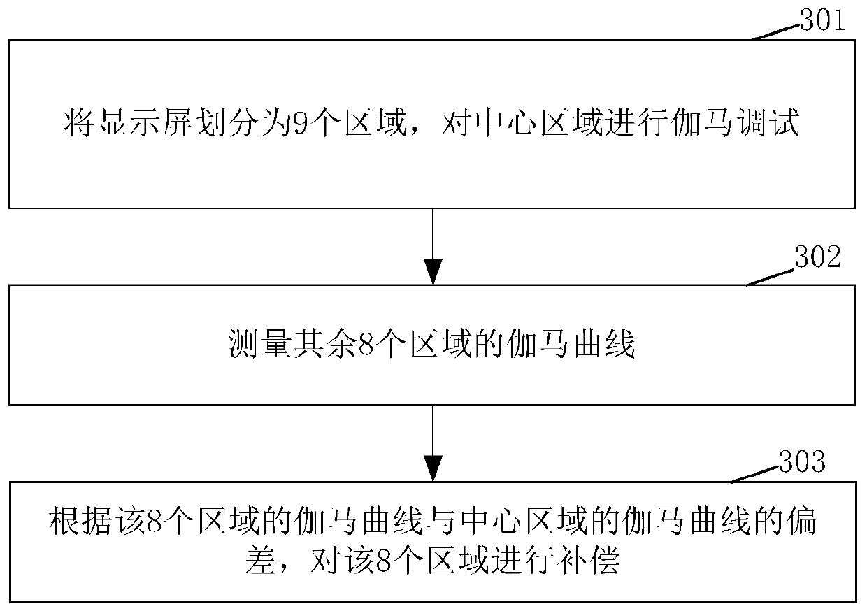
[0061] Such as image 3 Shown, including:
[0062] Step 301, for a large-size screen such as a vehicle, first divide the screen into 9 blocks, and first use a conventional method to perform Gamma tuning based on the center block (ie, zone A) to meet the standard Gamma2.2 curve.
[0063] Such as Figure 4 As shown, in 9 regions, the gamma value of the gamma curve of the central region is 2.2.
[0064] Step 302: Perform Gamma curve measurement of other blocks, and obtain Gamma curves of the remaining 8 blocks.
[0065] The gamma values of the Gamma curve of the 8 regions are 2.3, 2.1, 2.1, 2.4, 2.4, 2.1, 2.0, 2.3, such as Figure 4 As shown, it can be seen that there are deviations between the regions, so that under the same gray scale, the brightness is inconsistent and the uniformity is poor.
[0066] Step 303: Compensate the 8 regions according to the deviation of the Gamma curve of the 8 regions from the Gamma curve of the reference region, so that the Gamma curve of the 8 regions after compensation is consistent with the Gamma curve of the reference region.
[0067] Take one of the blocks( Figure 4 The area B) in the area of the compensation is described as an example.
[0068] Such as Figure 5 As shown, the gamma value of the Gamma curve measured in area B is 2.0 ( Figure 5 The solid line in the middle), compared to the Gamma curve 2.2 ( Figure 5 The middle dotted line) has a deviation. Select 10 gray levels or 10 points in the curve to calculate and compensate. It should be noted that the selection of these 10 points is variable, and the number of points will also change according to the actual status. More or fewer points can be selected, depending on the actual situation of the display at the time.
[0069] De-Gamma the Gamma curve and linearize the Gamma curve of the exponential function, such as Image 6 Shown.
[0070] The formula that the Gamma curve satisfies is: Lv=maximum brightness*[(GrayN-0)/(255-0)]^a
[0071] Take the logarithm of both ends of the above formula (in this embodiment, take the natural logarithm) to obtain the de-Gamma curve: ln(Lv)=ln{maximum brightness*[(GrayN-0)/(255-0)]^ a}=aln(GrayN))+K, where Lv is the brightness value, GrayN is the gray value, a is the Gamma value of the Gamma curve, K is the known value related to the maximum brightness, and the maximum brightness corresponds to the Gamma curve The maximum brightness.
[0072] Such as Image 6 As shown, at this time, two linear curves DeGamma=2.2 (obtained from the linearization of the Gamma curve of the central area A) and DeGamma=2.0 (obtained from the linearization of the Gamma curve of the area B) are obtained. The horizontal axis of the linear curve is the natural logarithm of the grayscale value, and the vertical axis is the natural logarithm of the brightness.
[0073] Calculate the deviation by linear curve, set 10 registers O1[7:0]~O10[7 in each block in IC (Integrated Circuit) or T-CON (Timing Controller, logic board) of large screen :0], each register is 8 bits (bit), each register corresponds to a gray scale, the offset value is calculated by comparing the difference between the linear curve of area B and the linear curve of area A in the same gray scale Y value , Calculate the compensation value of the gray scale according to the offset value, and record it in the corresponding register. Among them, the Y value is related to the brightness, and the brightness is related to the Gamma voltage. Therefore, the compensation value of the Gamma voltage can be calculated according to the difference of the Y value. The remaining gray levels are compensated by linear interpolation.
[0074] Finally, the compensated linear function changes it back to the Gamma curve, so that the Gamma curve of all blocks is finally pulled back to the target curve.
[0075] In this embodiment, the large-size screen is divided into multiple regions, one region is used as a reference region for Gamma debugging, and the remaining regions are subjected to Gamma compensation, which improves the uniformity of the display screen.
[0076] Such as Figure 7 As shown, an embodiment of the present application provides a gamma compensation device, including:
[0077] The gamma adjustment module 701 is configured to perform gamma adjustment on an area of the display screen to meet the target gamma curve, and the area is called a reference area;
[0078] The measurement module 702 is configured to measure one or more areas outside the reference area to obtain a first gamma curve of the area and a second gamma curve of the reference area;
[0079] The compensation module 703 is configured to determine the compensation value of the area according to the deviation between the first gamma curve and the second gamma curve, so that the gamma curve of the area after compensation is the same as the second gamma curve Consistent.
[0080] In an exemplary embodiment, the reference area is an area including the center point of the display screen.
[0081] In an exemplary embodiment, the compensation module 703 determining the compensation value of the region according to the deviation of the first gamma curve and the second gamma curve includes:
[0082] Convert the first gamma curve of the region into a first linear curve, convert the second gamma curve into a second linear curve, and determine according to the deviation of the first linear curve and the second linear curve The compensation value of this area.
[0083] Such as Figure 8 As shown, an embodiment of the present application provides a gamma compensation device 80, which includes a memory 810 and a processor 820. The memory 810 stores a program. When the program is read and executed by the processor 820, the gamma compensation device 80 is implemented. Horse compensation method.
[0084] Such as Picture 9 As shown, an embodiment of the present application provides a medium 90 on which is stored a computer program 910 that can run on a processor, and when the computer program 910 is executed by the processor, the steps of the gamma compensation method described above are implemented.
[0085] A person of ordinary skill in the art can understand that all or some of the steps in the methods, systems, and devices disclosed above can be implemented as software, firmware, hardware, and appropriate combinations thereof. In hardware implementations, the division between functional modules/units mentioned in the above description does not necessarily correspond to the division of physical components; for example, a physical component may have multiple functions, or a function or step may consist of several physical components. The components are executed cooperatively. Some or all components may be implemented as software executed by a processor, such as a digital signal processor or a microprocessor, or as hardware, or as an integrated circuit, such as an application specific integrated circuit. Such software may be distributed on a computer-readable medium, and the computer-readable medium may include a computer storage medium (or non-transitory medium) and a communication medium (or transitory medium). As is well known to those of ordinary skill in the art, the term computer storage medium includes volatile and non-volatile memory implemented in any method or technology for storing information (such as computer-readable instructions, data structures, program modules, or other data). Flexible, removable and non-removable media. Computer storage media include but are not limited to RAM, ROM, EEPROM, flash memory or other memory technology, CD-ROM, digital versatile disk (DVD) or other optical disk storage, magnetic cassette, tape, magnetic disk storage or other magnetic storage device, or Any other medium used to store desired information and that can be accessed by a computer. In addition, as is well known to those of ordinary skill in the art, communication media usually contain computer-readable instructions, data structures, program modules, or other data in a modulated data signal such as carrier waves or other transmission mechanisms, and may include any information delivery media .
[0086] Although the embodiments disclosed in the present invention are as above, the content described is only the embodiments used to facilitate the understanding of the present invention, and is not intended to limit the present invention. Anyone skilled in the art to which the present invention belongs can make any modifications and changes in the implementation form and details without departing from the spirit and scope of the present invention. However, the patent protection scope of the present invention still requires The scope defined by the appended claims shall prevail.