
Plasma surgical equipment connector capable of meeting safe creepage distance

A connector and plasma technology, applied in the direction of connection, two-part connection device, parts of the connection device, etc., can solve the problems of low stability and reliability of plasma surgery equipment, short creepage distance, damage to connectors and hosts, etc. , to enhance reliability and tensile strength, prevent creepage spread and avoid short circuit

Pending Publication Date: 2020-05-29
NANJING ECO MICROWAVE SYST
View PDF0 Cites 0 Cited by
  • Summary
  • Abstract
  • Description
  • Claims
  • Application Information

AI Technical Summary

Problems solved by technology

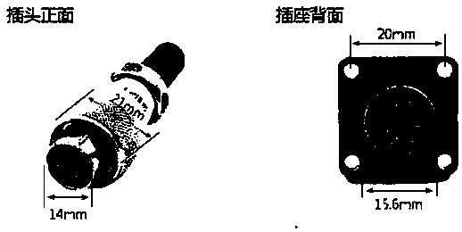
The diameter of the socket hole is about 16mm, the diameter of the contact pin is about Φ1.5mm, the furthest distance between the contact diameters is about 10.5mm, and the furthest distance between adjacent contact diameters is about 3mm. Beautiful, but because of the small size of the connector, the diameter of the built-in pin is relatively thin. The connector signal connection electrical performance cables are distributed in a circular shape, and the structural spacing is compact. When the high-frequency energy signal and the detection signal pass through the connector at the same time, The creepage distance is short, which can easily lead to electrical damage to the plasma surgical equipment connector and the host, making the stability and reliability of the plasma surgical equipment low in use

Method used


Image

  • Plasma surgical equipment connector capable of meeting safe creepage distance
  • Plasma surgical equipment connector capable of meeting safe creepage distance
  • Plasma surgical equipment connector capable of meeting safe creepage distance

Examples


Embodiment Construction

[0024] The present invention will be described in detail below in conjunction with the accompanying drawings.

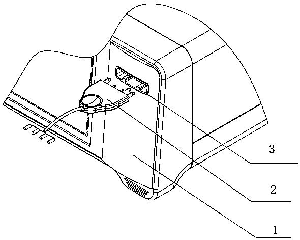
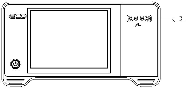
[0025] Such as figure 2 As shown, the connector of this embodiment is composed of a main body connector 2 and a receptacle connector 3 . The main body connector 2 is arranged at the tail of the plasma accessory; the socket connector 3, such as image 3 As shown, it can be fitted with the main body connector 2, and the socket connector is arranged on the panel of the main body 1 of the plasma surgical equipment.

[0026] Such as Figure 4 As shown, the main body connector 2 is composed of an insulating main body outer plastic shell and several main body connecting pins, the outer plastic shell is made of insulating ABS resin material, and a number of pins are provided inside to allow the pins to be inserted. hole, the pin is installed in the plastic case after being inserted into the socket. The contact parts of the above-mentioned plurality of main body connecti...


PUM


Abstract

The invention relates to a connector, particularly relates to a connector capable of increasing a safe creepage distance, and belongs to the technical field of plasma surgical equipment connectors. According to the technical scheme provided by the invention, the plasma surgical equipment connector capable of meeting the creepage distance comprises a main body connector and a socket connector. Themain body connector is provided with an outer plastic shell and a plurality of main body connecting contact pins, contact parts in the plurality of main body connecting contact pins are arranged in parallel along a direction vertical to a surface of the outer plastic shell, and an embedding direction is staggered by an L1 interval; and the socket connector is provided with socket outer plastic shells and a plurality of socket connecting points, the socket outer plastic shells can be embedded with the main body shell, in the plurality of socket connecting points, when the two outer plastic shells are embedded, the contact parts are respectively inserted, pin positioning grooves at two ends of each outer plastic shell are provided with insulating embossment partition walls, and an anti-creepage insulating step is formed by the insulating embossment partition walls and pins adjacent to an inner side. In the invention, the creepage distance can be increased, and stability and reliability of the plasma surgical equipment connector are improved.

Description

technical field [0001] The invention relates to a connector, in particular to a plasma surgical equipment connector capable of satisfying a safe creepage distance, and belongs to the technical field of electrical connection device manufacturing. Background technique [0002] Plasma surgery equipment connectors are mainly used to connect the main unit of plasma surgery equipment and plasma accessories, and are used to accept the high-frequency energy output from the main unit and input it to the electrode part. Since the output high-voltage high-frequency energy is a variable range, especially in high-energy When the output is high, the electrical performance requirements of the connector are very high. At present, most of the energy output connectors designed for mainstream plasma surgery equipment in the market are circular multi-core aviation socket connectors. [0003] figure 1 It is a schematic diagram of the mainstream plasma surgery equipment connectors on the market...

Claims


Application Information

Patent Timeline
IPC IPC(8): H01R13/17H01R13/53H01R13/58H01R24/28H01R27/02
CPCH01R13/17H01R13/53H01R13/5833H01R24/28H01R27/02
Inventor 李杰张磊孙良俊
Owner NANJING ECO MICROWAVE SYST
Learn More