Automatic aluminum rotary rod shaft head knurling device

A knurling and rod shaft technology is applied in the field of automatic aluminum rotary rod shaft head knurling device, which can solve the problems of complicated operation and low processing efficiency of workpiece knurling, and achieve the effects of simple operation, convenient cutting and improving efficiency.

Active Publication Date: 2020-06-02
山东齐昊新型彩铝有限公司
View PDF5 Cites 0 Cited by
  • Summary
  • Abstract
  • Description
  • Claims
  • Application Information

AI Technical Summary

Problems solved by technology

[0004] In order to overcome the shortcomings of the existing knurling processing equipment for the shaft head of the aluminum rotary rod, the operation is complicated, and the workpiece knurling processing efficiency is low. Knurling device for rotary shaft head

Method used


Image

  • Automatic aluminum rotary rod shaft head knurling device
  • Automatic aluminum rotary rod shaft head knurling device
  • Automatic aluminum rotary rod shaft head knurling device

Examples


Embodiment 1

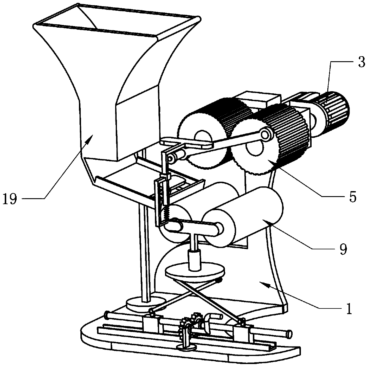
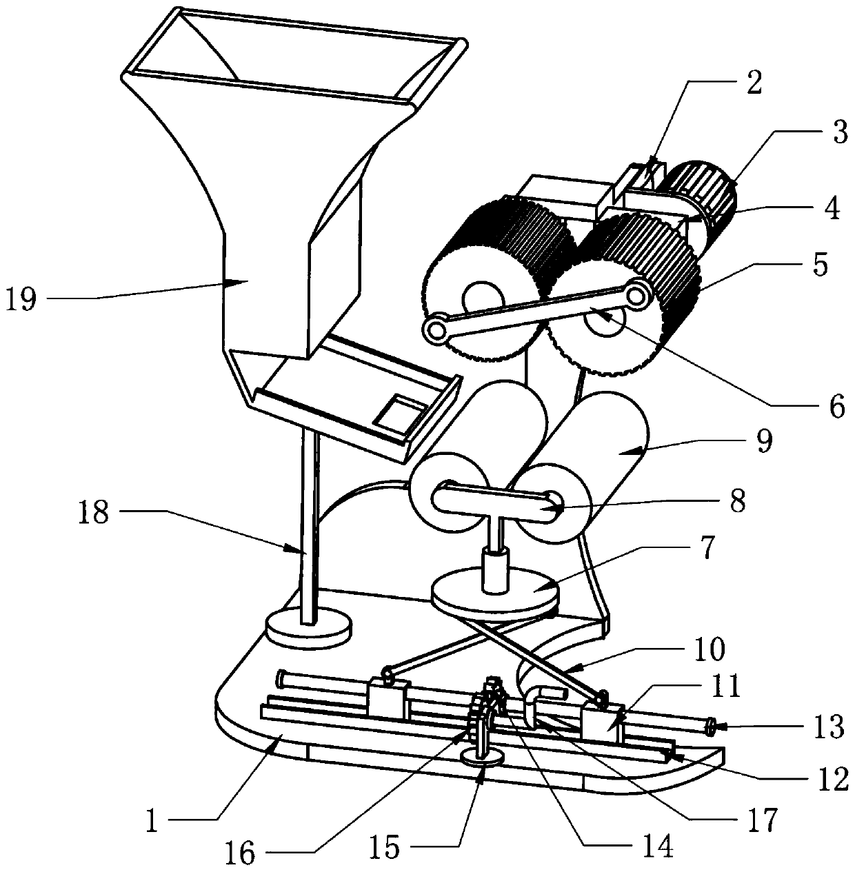
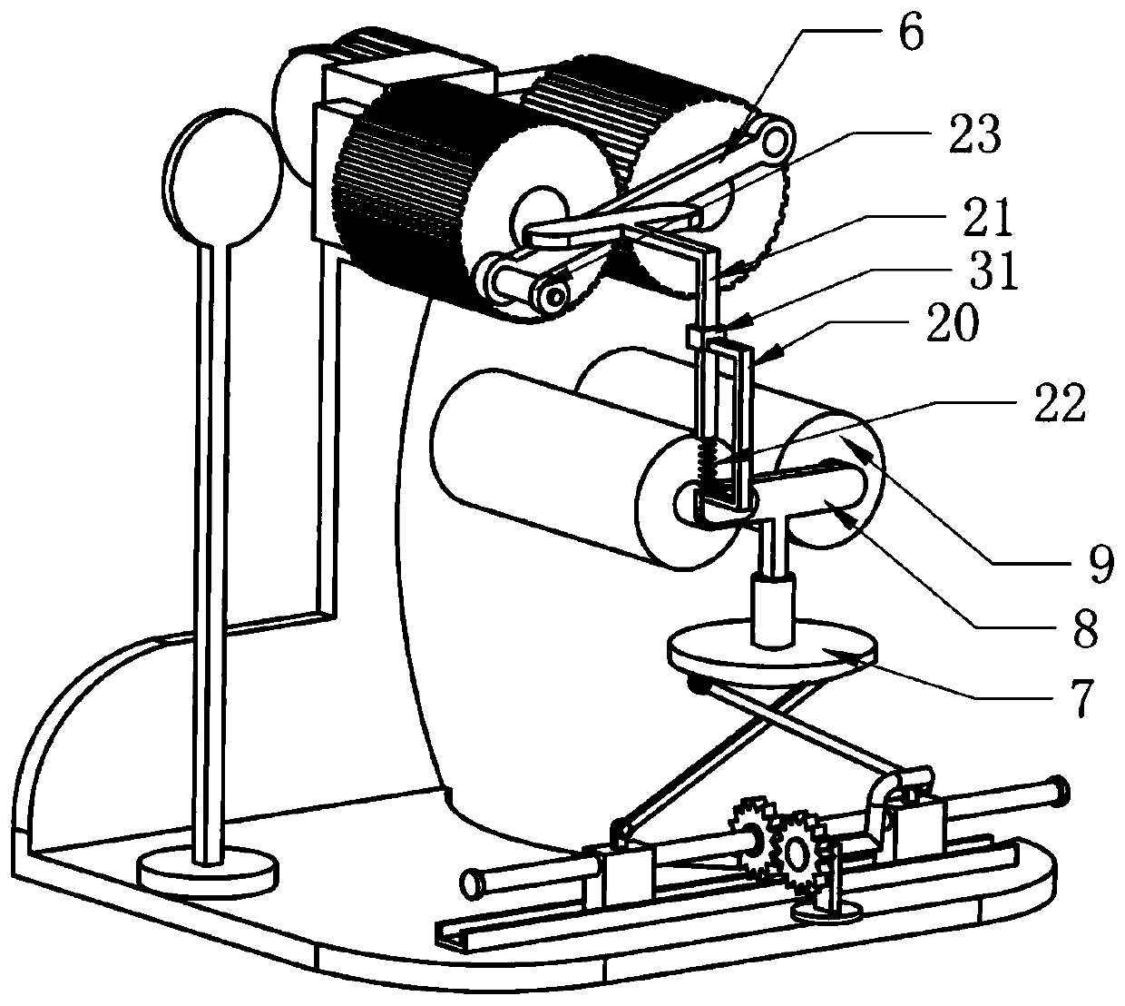
[0021] An automatic aluminum rotary rod shaft head knurling device, such as Figure 1-5 As shown, it includes a frame 1, a motor base 2, a servo motor 3, a rotating base 4, a knurled wheel 5, a connecting rod 6, a fixed rod 18 and a discharge hopper 19, and the motor base 2 is fixedly installed on the frame 1 , the servo motor 3 is fixedly installed on the motor base 2, the rotating base 4 is fixedly installed on the frame 1 and is located on the front side of the motor base 2, and the rotating base 4 is equipped with two rotating shafts for aligning aluminum Two knurling wheels 5 for performing knurling processing operations on the shaft head workpiece of the rotary rod, and the knurling wheel 5 on the right side of the rotating seat 4 is connected to the output end of the servo motor 3 through a rotating shaft, and the two knurling wheels 5 The front end of the front end is connected to the connecting rod 6 through the rotating column. The fixed rod 18 is fixedly installed o...

Embodiment 2

[0027] An automatic aluminum rotary rod shaft head knurling device, such as Figure 1-5 As shown, it includes a frame 1, a motor base 2, a servo motor 3, a rotating base 4, a knurled wheel 5, a connecting rod 6, a fixed rod 18 and a discharge hopper 19, and the motor base 2 is fixedly installed on the frame 1 , the servo motor 3 is fixedly installed on the motor base 2, the rotating base 4 is fixedly installed on the frame 1 and is located on the front side of the motor base 2, and the rotating base 4 is equipped with two rotating shafts for aligning aluminum Two knurling wheels 5 for performing knurling processing operations on the shaft head workpiece of the rotary rod, and the knurling wheel 5 on the right side of the rotating seat 4 is connected to the output end of the servo motor 3 through a rotating shaft, and the two knurling wheels 5 The front end of the front end is connected to the connecting rod 6 through the rotating column. The fixed rod 18 is fixedly installed o...


PUM


Abstract

The invention relates to the technical field of aluminum rotary rod shaft head machining, in particular to an automatic aluminum rotary rod shaft head knurling device. The automatic aluminum rotary rod shaft head knurling device provided by the invention is high in workpiece knurling and machining efficiency, easy to operate and wide in application range. According to the technical scheme, the automatic aluminum rotary rod shaft head knurling device comprises a rack, a motor base, a servo motor, a rotary seat, knurling rollers and the like. The motor base is fixedly mounted on the rack. The servo motor is fixedly mounted on the motor base. The rotary seat is fixedly mounted on the rack. The two knurling rollers are mounted on the rotary seat through two rotary shafts. Through cooperation of press rollers and a swing rod, the automatic aluminum rotary rod shaft head knurling device can enable workpieces to be knurled in a discharge hopper to pass through a baffle and slide onto the twopress rollers one by one. The automatic aluminum rotary rod shaft head knurling device facilitates discharging and is high in machining efficiency, capable of meeting the requirements for knurling ofworkpieces with different thicknesses and wide in application range.

Description

technical field [0001] The invention relates to the technical field of spindle head processing of a rotary rod, in particular to an automatic knurling device for the spindle head of a rotary rod made of aluminum. Background technique [0002] Knurling refers to a mechanical process of rolling patterns on the handles of metal products or other working surfaces. The main function is to increase the slip resistance of the workpiece. The method is to roll the surface of the workpiece with a knurling knife or knurling wheel. Straight grain or net grain, after the workpiece is knurled, it can increase the aesthetic feeling and be easy to handle. [0003] The existing knurling processing equipment for the aluminum rotary rod shaft head cannot realize the integrated automatic operation of blanking and knurling of the aluminum rotary rod shaft head workpiece when knurling the aluminum rotary rod shaft head. Complicated, resulting in low efficiency of workpiece knurling processing, a...

Claims


Application Information

Patent Timeline
Patent Type & Authority Applications(China)
IPC IPC(8): B23P9/02
CPCB23P9/02
Inventor 曹宗荣
Owner 山东齐昊新型彩铝有限公司
Why Eureka
Try Eureka