
Roller machining device with limiting mechanism

A technology of limiting mechanism and processing device, applied in the field of roller processing, can solve the problems of left and right shaking, roller slipping out, poor processing quality, etc., to achieve a good limiting effect and ensure the effect of normal processing

Pending Publication Date: 2020-06-02
青岛盛宏源机械制造有限公司
View PDF0 Cites 0 Cited by
  • Summary
  • Abstract
  • Description
  • Claims
  • Application Information

AI Technical Summary

Problems solved by technology

[0003] When the traditional roller is transported to the support frame through the conveying equipment during processing, the holding platform is just a single arc-shaped plate, which is easy to cause the roller to slip out, and the turret is raised under the drive of the hydraulic rod, and then the roller Slide into a barrel-shaped frame, but for rollers of different widths, the barrel-shaped frame cannot achieve the purpose of limiting it, and it is easy to shake left and right during processing, resulting in poor processing quality. Therefore, a solution is proposed to solve the above problems A processing device for a roller with a limit mechanism

Method used


Image

  • Roller machining device with limiting mechanism
  • Roller machining device with limiting mechanism
  • Roller machining device with limiting mechanism

Examples


Embodiment Construction

[0019] The following will clearly and completely describe the technical solutions in the embodiments of the present invention with reference to the accompanying drawings in the embodiments of the present invention. Obviously, the described embodiments are only some, not all, embodiments of the present invention. Based on the embodiments of the present invention, all other embodiments obtained by persons of ordinary skill in the art without making creative efforts belong to the protection scope of the present invention.

[0020] see Figure 1-3 , the present invention provides a technical solution:

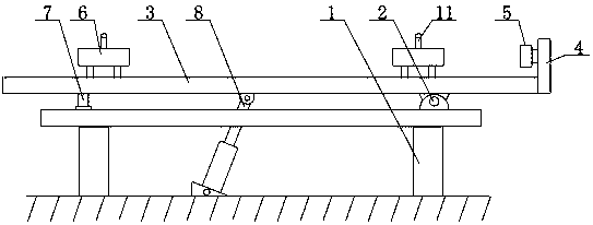
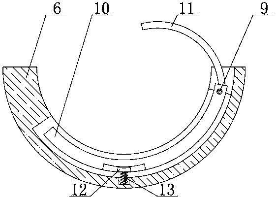
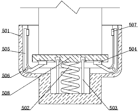
[0021] A processing device for a roller with a limit mechanism, comprising a support frame 1 and a rotating block 2, the right side of the upper end surface of the support frame 1 is fixedly connected with the rotating block 2, the upper end surface of the rotating block 2 is fixedly connected with a turret 3, and the turret 3 The upper end surface is fixedly connected with the ho...


PUM


Abstract

The invention relates to the technical field of roller machining, in particular to a roller machining device with a limiting mechanism. A supporting frame and a rotation block are included. The rightside of the upper end face of the supporting frame is fixedly connected with the rotation block. The upper end face of the rotation block is fixedly connected with a rotation frame. The upper end faceof the rotation frame is fixedly connected with containing tables distributed left and right. The lower end face of the rotation frame is rotationally connected with a hydraulic rod. A cushion plateis arranged on the left side of the hydraulic rod. The upper end face of the cushion plate is fixedly connected with the rotation frame. A fixing plate is fixedly connected to the right end face of the rotation frame. The limiting mechanism is fixedly connected to the left end face of the fixing plate. In the roller machining device, through the arranged containing tables, arranged arc plates andarranged protection plates, when rollers are transported into the containing tables, the rollers press the arc plates, accordingly, tensioning springs are compressed, the arc plates drive the protection plates to rotate at the time, the protection plates are located above the rollers, the rollers are prevented from sliding out of the containing tables, and a very good limiting function is achieved.

Description

technical field [0001] The invention relates to the technical field of drum processing, in particular to a drum processing device with a limiting mechanism. Background technique [0002] The cylinder is a cylindrical part, divided into driving and driven rollers. It is widely used in various transmission systems such as rotary screen printing machines, digital printers, conveying equipment, papermaking and packaging machinery. It is usually made of seamless steel pipes, and there are also Depending on the needs of different processes, materials such as aluminum alloy 6061T5, 304L / 316L stainless steel, 2205 duplex stainless steel, steel castings, and solid forged alloy steel cores are used. [0003] When the traditional roller is transported to the support frame through the conveying equipment during processing, the holding platform is just a single arc-shaped plate, which is easy to cause the roller to slip out, and the turret is raised under the drive of the hydraulic rod, ...

Claims


Application Information

Patent Timeline
Patent Type & Authority Applications(China)
IPC IPC(8): B23Q3/08B23Q7/00
CPCB23Q3/062B23Q3/082B23Q7/00
Inventor 管洪运张瑞芳
Owner 青岛盛宏源机械制造有限公司
Learn More