
Vehicle body structure and vehicle

A body and vehicle technology, applied in the field of vehicle collision safety, can solve problems such as insufficient connection strength, unfavorable collision force dispersion, and structural damage

Inactive Publication Date: 2020-06-02
BORGWARD AUTOMOTIVE CHINA CO LTD
View PDF10 Cites 0 Cited by
  • Summary
  • Abstract
  • Description
  • Claims
  • Application Information

AI Technical Summary

Problems solved by technology

[0002] The rear end of the energy-absorbing box of a traditional vehicle is connected to the longitudinal beam, and the front end is connected to the front anti-collision beam. When the vehicle is in a frontal collision and the energy-absorbing boxes on the left and right sides are stressed at the same time, the energy-absorbing box can have a relatively ideal performance. However, when the energy-absorbing box on one side is stressed, the connection strength of the energy-absorbing box on the other side will be insufficient, resulting in joint tearing at the connection between the rear end of the energy-absorbing box on the other side and the longitudinal beam
Moreover, when the vehicle collides head-on, the collision force can only be transmitted backward along the path of the front anti-collision beam-absorbing box-longitudinal beam. The force transmission path is single, which is not conducive to the dispersion of the collision force, resulting in large deformation of the vehicle body
In addition, due to the low coverage ratio of the front anti-collision beam in the vehicle width direction, in the event of a frontal collision with a small overlapping area, the energy-absorbing box may not be able to absorb energy, resulting in a large amount of intrusion into the passenger compartment structure and serious structural damage

Method used


Image

  • Vehicle body structure and vehicle
  • Vehicle body structure and vehicle
  • Vehicle body structure and vehicle

Examples


Embodiment Construction

[0031] Specific embodiments of the present disclosure will be described in detail below in conjunction with the accompanying drawings. It should be understood that the specific embodiments described here are only used to illustrate and explain the present disclosure, and are not intended to limit the present disclosure.

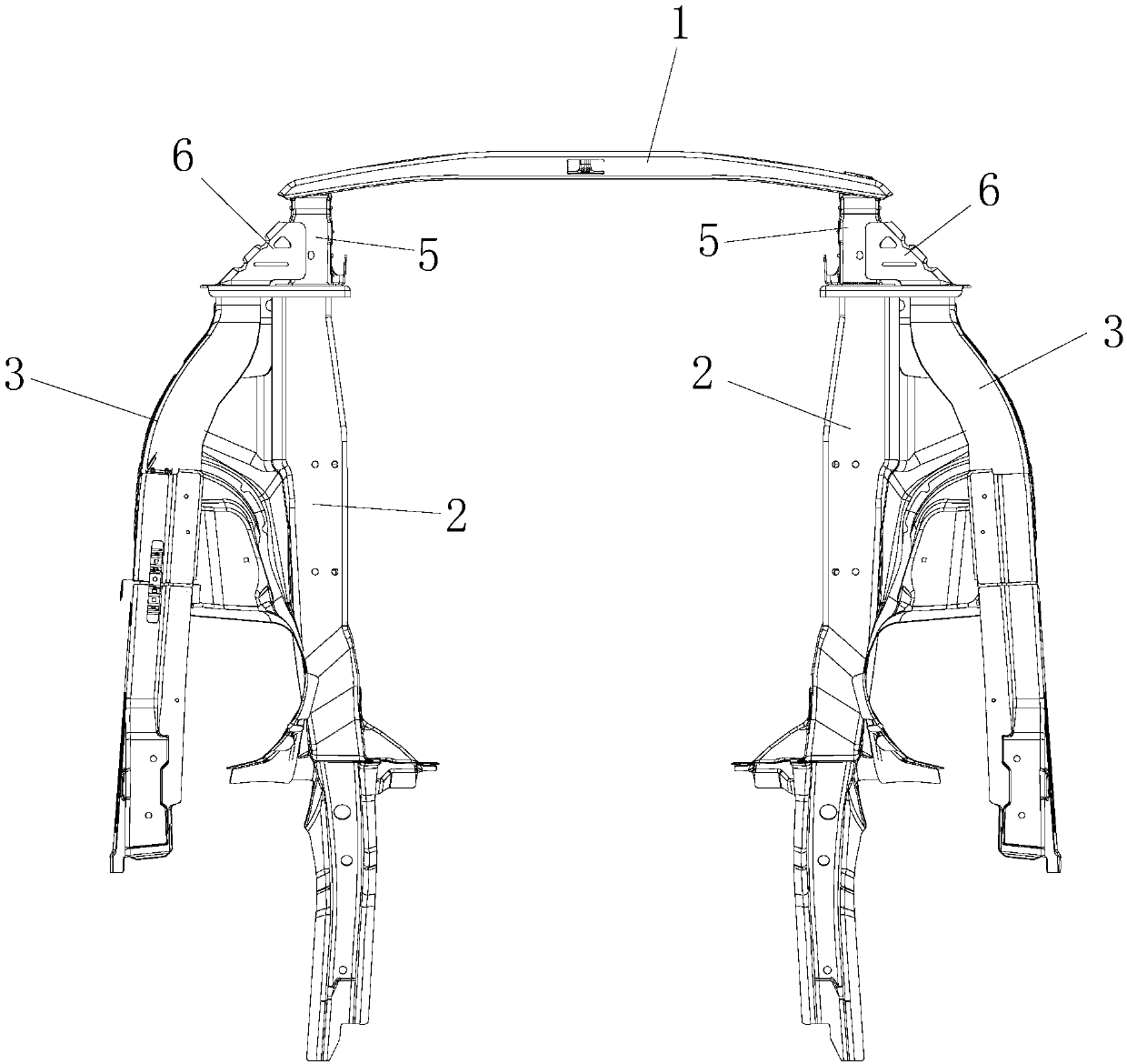
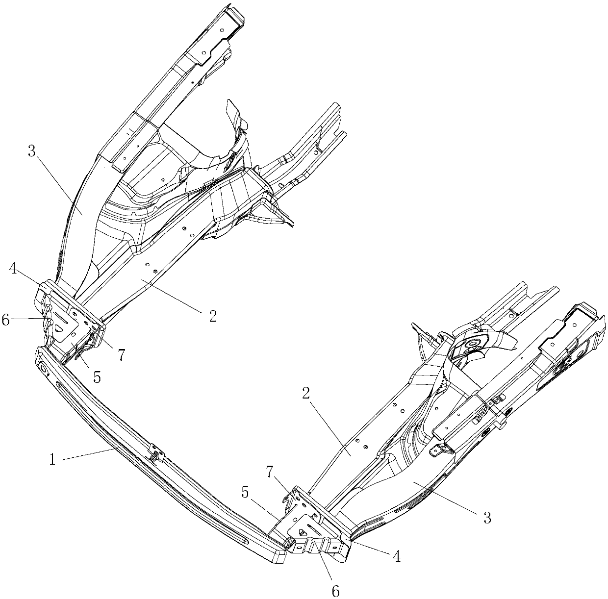
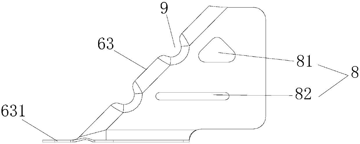
[0032] Such as Figure 1 to Figure 5 As shown, the present disclosure provides a vehicle body structure, which includes a front anti-collision beam 1, a longitudinal beam 2, a side reinforcement beam 3, a front end cover plate 4 and an energy absorbing box, and the energy absorbing box may be a sheet metal part , while being easy to process, it can improve the connection strength between structures. The crash box includes a main body 5 and a branch 6 protruding from the main body 5. The lateral branch 6 along the vehicle body is located outside the main body 5. The front ends of the longitudinal beams 2 and the side reinforcement beams 3 are connected to Th...


PUM


Abstract

The invention relates to a vehicle body structure and a vehicle. The vehicle body structure comprises a front anti-collision beam, longitudinal beams, side edge reinforcing beams, a front end cover plate and an energy absorption box. The energy absorption box is a sheet metal part, and comprises a main body part and branch parts extending out of the main body part, the branch parts are located onthe outer side of the main body part in the transverse direction of the automobile body, the front ends of the longitudinal beams and the front ends of the side edge reinforcing beams are connected tothe front end cover plate, the front end of the main body part is connected to the front anti-collision beam, and the rear end of the main body part and the rear ends of the branch parts are all connected to the front end cover plate. By additionally arranging the branch parts, the connecting strength of the main body part and the front end cover plate can be improved, when the main body part onone side is stressed, the main body part on the other side cannot be torn, and the structural stability is high.

Description

technical field [0001] The present disclosure relates to the technical field of vehicle collision safety, and in particular, relates to a vehicle body structure and a vehicle. Background technique [0002] The rear end of the energy-absorbing box of a traditional vehicle is connected to the longitudinal beam, and the front end is connected to the front anti-collision beam. When the vehicle has a frontal collision and the energy-absorbing boxes on the left and right sides are stressed at the same time, the energy-absorbing box can have a relatively ideal performance. However, when the energy-absorbing box on one side is stressed, the connection strength of the energy-absorbing box on the other side will be insufficient, resulting in joint tearing at the connection between the rear end of the energy-absorbing box on the other side and the longitudinal beam. Moreover, when the vehicle collides head-on, the collision force can only be transmitted backward along the path of the f...

Claims


Application Information

Patent Timeline
Patent Type & Authority Applications(China)
IPC IPC(8): B62D21/15
CPCB62D21/15
Inventor 张洁曾榕
Owner BORGWARD AUTOMOTIVE CHINA CO LTD
Learn More