Gravity-operated tube filler and method for gravity-operated filling of beverages

A filler and beverage technology, applied in the field of gravity filling beverages and gravity short tube fillers

Active Publication Date: 2020-06-02
KRONES AG
View PDF8 Cites 0 Cited by
  • Summary
  • Abstract
  • Description
  • Claims
  • Application Information

AI Technical Summary

Problems solved by technology

However, this results in undesired restrictions on the design of the gravity spool filler

Method used


Image

  • Gravity-operated tube filler and method for gravity-operated filling of beverages
  • Gravity-operated tube filler and method for gravity-operated filling of beverages

Examples


Embodiment Construction

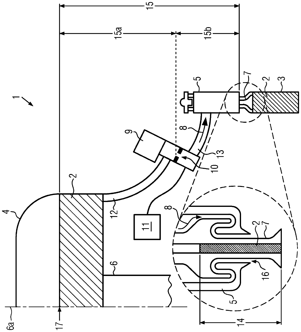
[0028] like figure 1 As can be seen in a schematic partial view, a gravity stub filler 1 for filling beverages 2, such as spirits, wine or similar liquid products, into bottles 3 comprises a product pot 4 and a plurality of The filling valves 5 (only one of which is shown) can be opened and closed in a known manner by squeezing and removing the bottle 3 .

[0029] The gravity spool filler 1 is preferably of circumferential construction, so that the product pot 4 , which can also be designed, for example, as a ring pot (not shown), and the filling valve 5 are arranged on the rotor of the filler turret 6 . this is in figure 1 is illustrated schematically by the axis of rotation 6a.

[0030] as especially from figure 1 As can be seen in the enlarged section in , the filling valve 5 includes a gas return duct 7 which is closed airtight by the raised beverage 2 at the end of the respective filling process, whereby the beverage flows into 8 (product inflow) slowly stops.

[003...


PUM


Abstract

The invention relates to a gravity-operated tube filler and a method for gravity-operated filling of beverages. The gravity-operated tube filler comprises a product cooker and a filling valve which isconnected with the product cooker. The filling valve is constructed to restrict the filling height in a bottom by means of an air returning tube. Because an adjusting value is speficially arranged infront of the filling valve, the adjusting valve is used for shuttling beverage infilling to the filling valve in a machine-controllable manner so that the influence of the pressure of static fluid between the beverage in the product cooker and the filling valve can be reduced in a targeted manner. Therefore, the lifting height of the bevere in the air returning tube reduces, and furthermore the filling height can be accurately adjusted on the condition of no probe for filling height correction or filling height monitoring.

Description

technical field [0001] The invention relates to a gravity stub filler according to the preamble of claim 1 and a method for gravity filling beverages according to the preamble of claim 9 . Background technique [0002] For filling beverages, such as spirits, wine or similar liquid products into bottles, known gravity stub fillers have proven effective. During filling there is then a constant pressure between the product pot with the beverage to be filled present on the gravity stub filler and the interior of the bottle to be filled. This constant pressure can exist not only at ambient pressure but also at excess pressure, for example for filling carbonated beverages. [0003] In such a filler, the filling height is preferably adjusted via the length of the return line formed on the filling valve in such a way that the filled beverage is raised until it reaches the free end of the return line and is airtight. Permanently close the trachea. Thus, the injection of the bevera...

Claims


Application Information

Patent Timeline
Patent Type & Authority Applications(China)
IPC IPC(8): B67D1/12
CPCB67D1/1279B67C3/286B67C3/262B67C3/2628
Inventor 斯特凡·珀施尔弗朗茨·奥伯迈尔
Owner KRONES AG
Why Eureka
Try Eureka