
Backlight source and display device

A backlight and light source technology, applied in optics, nonlinear optics, instruments, etc., can solve problems such as uneven brightness of display devices, high precision requirements for shading glue process, poor display effect of display devices, etc., to avoid optical quality bad effect

Active Publication Date: 2020-06-02
BOE TECH GRP CO LTD +1
View PDF11 Cites 3 Cited by
  • Summary
  • Abstract
  • Description
  • Claims
  • Application Information

AI Technical Summary

Problems solved by technology

[0002] The liquid crystal display device mainly includes a display panel and a backlight. The backlight includes a light source, a light guide plate and an optical film. On one side of the light source, part of the light from the light source will directly shine on the optical film. In order to prevent the light directly irradiated on the optical film from entering the display panel, a light-shielding glue will be attached to the optical film to prevent the direct light from entering the display panel. The light on the optical film is blocked, but the process precision of the light-shielding adhesive is high, and a slight error will cause the light emitted by the light source to pass through the optical film and irradiate the display panel directly, which in turn will cause the brightness of the display device to appear. The problem of poor optical quality due to unevenness makes the display effect of the display device unsatisfactory

Method used


Image

  • Backlight source and display device
  • Backlight source and display device
  • Backlight source and display device

Examples


Embodiment Construction

[0034] In order to further explain the technical means and effects of the present invention to achieve the intended purpose of the invention, the specific implementation, structure and characteristics of a backlight source and display device proposed according to the present invention will be described below in conjunction with the accompanying drawings and preferred embodiments. and its efficacy are described in detail below.

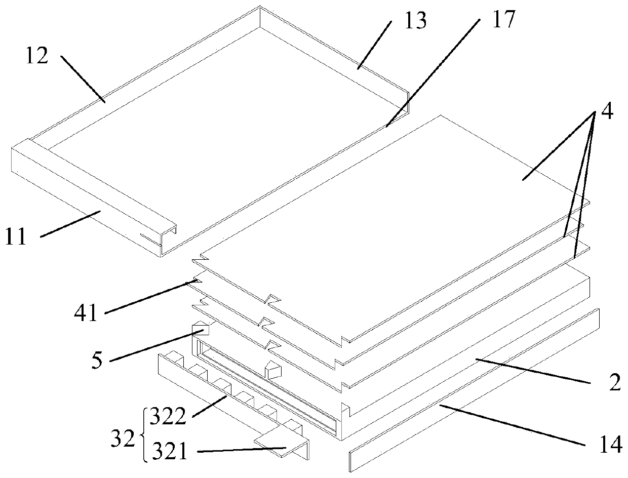
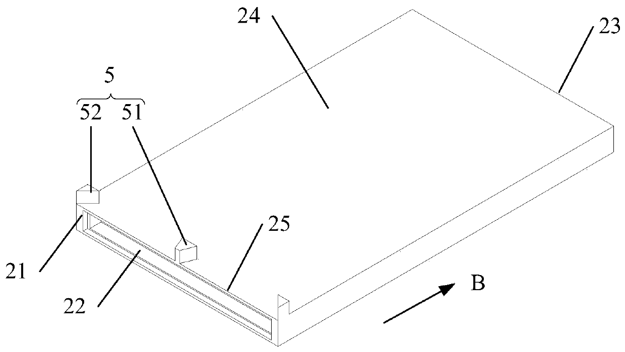
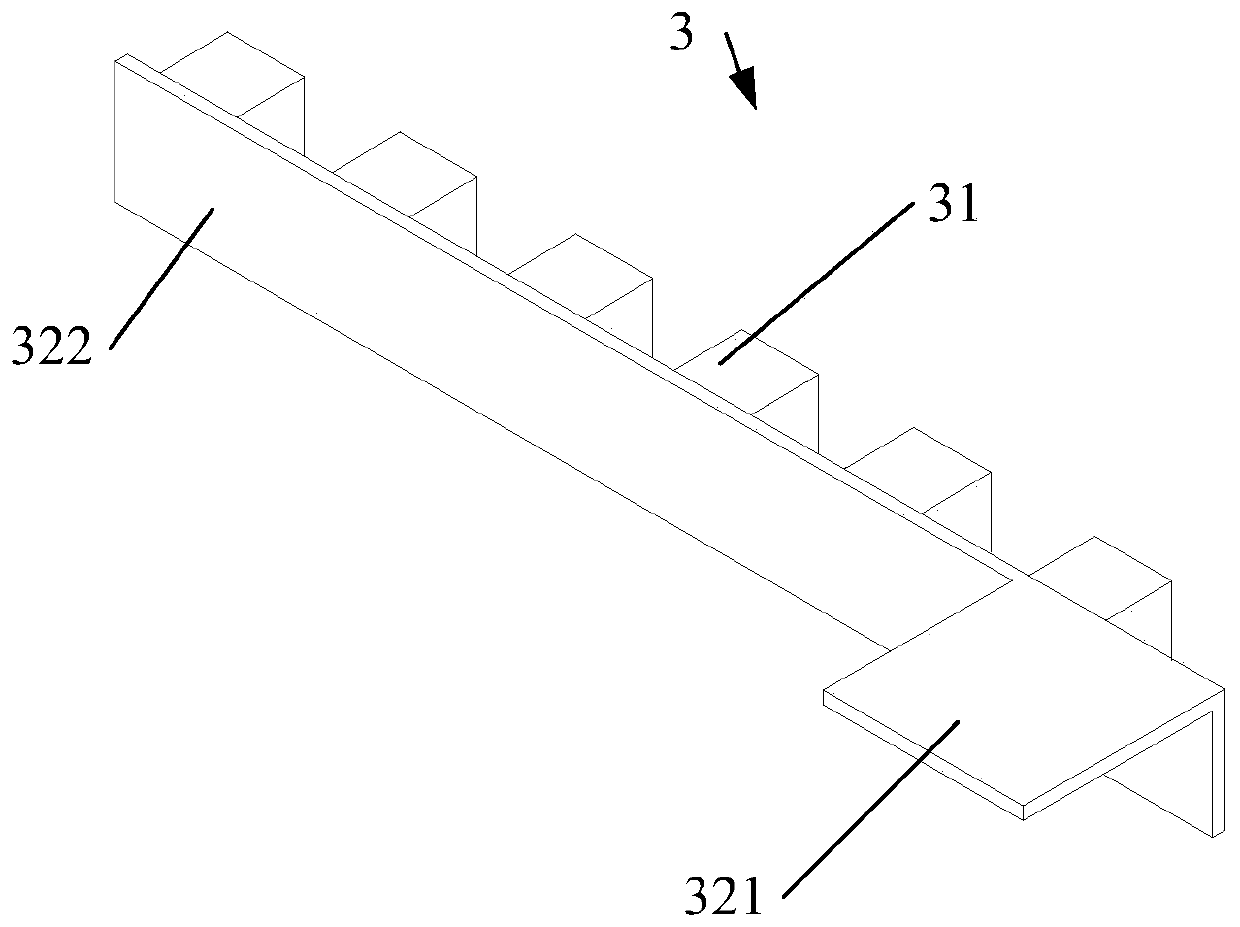
[0035] On the one hand, if Figure 1 to Figure 7 As shown, the embodiment of the present invention provides a backlight, the backlight comprises: a backplane 1, the backplane 1 is formed with an accommodation groove 18; a light guide plate 2, the first side 21 of the light guide plate 2 is formed with an accommodation groove 22 ; the light source 3 , at least part of the light source 3 is arranged in the receiving groove 22 , wherein the light guide plate 2 and the light source 3 are both arranged in the receiving groove 18 . The light source 3 can be...


PUM


Abstract

The invention discloses a backlight source and a display device, relates to the technical field of display, and achieves the purpose of improving the display effect of the display device. According tothe main technical scheme of the invention, the device comprises: a back plate, wherein a containing groove is formed in the back plate; a light guide plate, wherein an accommodating groove is formedin the first side surface of the light guide plate; a light source, wherein at least part of the light source is arranged in the accommodating groove; the light guide plate and the light source are both arranged in the containing groove. The invention is mainly used for manufacturing the backlight source.

Description

technical field [0001] The invention relates to the field of display technology, in particular to a backlight source and a display device. Background technique [0002] The liquid crystal display device mainly includes a display panel and a backlight. The backlight includes a light source, a light guide plate and an optical film. On one side of the light source, part of the light from the light source will directly shine on the optical film. In order to prevent the light directly irradiated on the optical film from entering the display panel, a light-shielding glue will be attached to the optical film to prevent the direct light from entering the display panel. The light on the optical film is blocked, but the process precision of the light-shielding adhesive is high, and a slight error will cause the light emitted by the light source to pass through the optical film and irradiate the display panel directly, which in turn will cause the brightness of the display device to ap...

Claims


Application Information

Patent Timeline
IPC IPC(8): G02F1/13357
CPCG02F1/1336G02F1/133608G02F1/133606G02F1/133611G02B6/0021G02B6/0088G02B6/0083G02B6/0055G02F1/133314G02F1/133325
Inventor 郝瑞军连龙石天雷唐乌力吉白尔李岳峰赵忠平王晓杰宁伟郭飞翔张学峰胡海芳吴永凯孙乐
Owner BOE TECH GRP CO LTD
Learn More