
Cutting device for spinning

A cutting equipment and textile technology, applied in the direction of textiles and papermaking, textile material cutting, metal processing, etc., can solve the problem of low work efficiency, achieve the effect of improving work efficiency and ensuring efficiency

Active Publication Date: 2020-06-05
临沂协润工贸有限公司
View PDF9 Cites 5 Cited by
  • Summary
  • Abstract
  • Description
  • Claims
  • Application Information

AI Technical Summary

Problems solved by technology

[0003] In the actual production process, sometimes it is necessary to cut textiles. The existing cutting device needs to manually control the movement of the cutting head to complete the cutting of textiles, and the work efficiency is low.

Method used


Image

  • Cutting device for spinning
  • Cutting device for spinning
  • Cutting device for spinning

Examples


Embodiment Construction

[0042] The technical solutions in the embodiments of the present invention will be clearly and completely described below with reference to the accompanying drawings in the embodiments of the present invention. Obviously, the described embodiments are only a part of the embodiments of the present invention, rather than all the embodiments. Based on the embodiments of the present invention, all other embodiments obtained by those of ordinary skill in the art without creative efforts shall fall within the protection scope of the present invention.

[0043] In the description of the present invention, it is to be understood that the terms "opening", "upper", "lower", "thickness", "top", "middle", "length", "inside", "around", etc. Indicates the orientation or positional relationship, only for the convenience of describing the present invention and simplifying the description, rather than indicating or implying that the components or elements referred to must have a specific orient...


PUM


Abstract

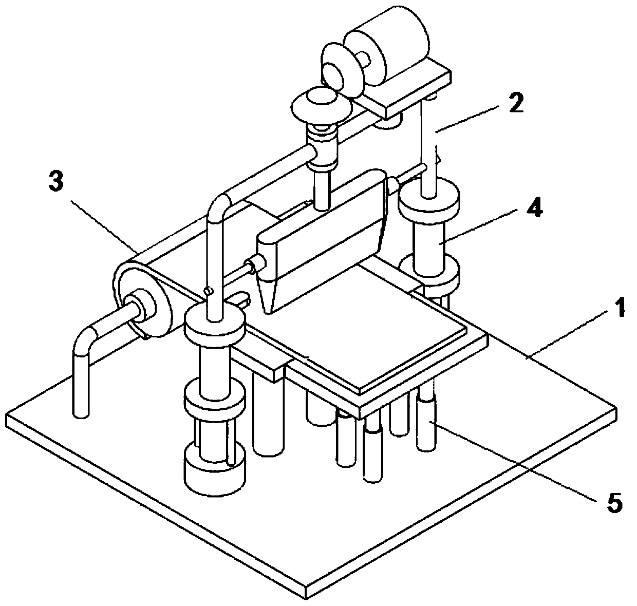
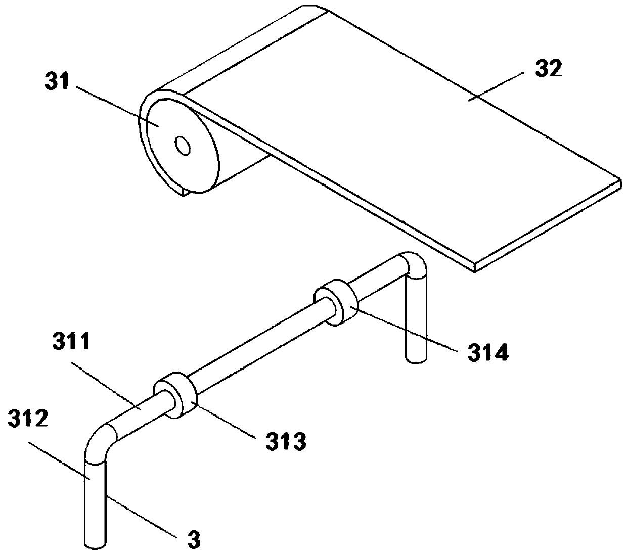
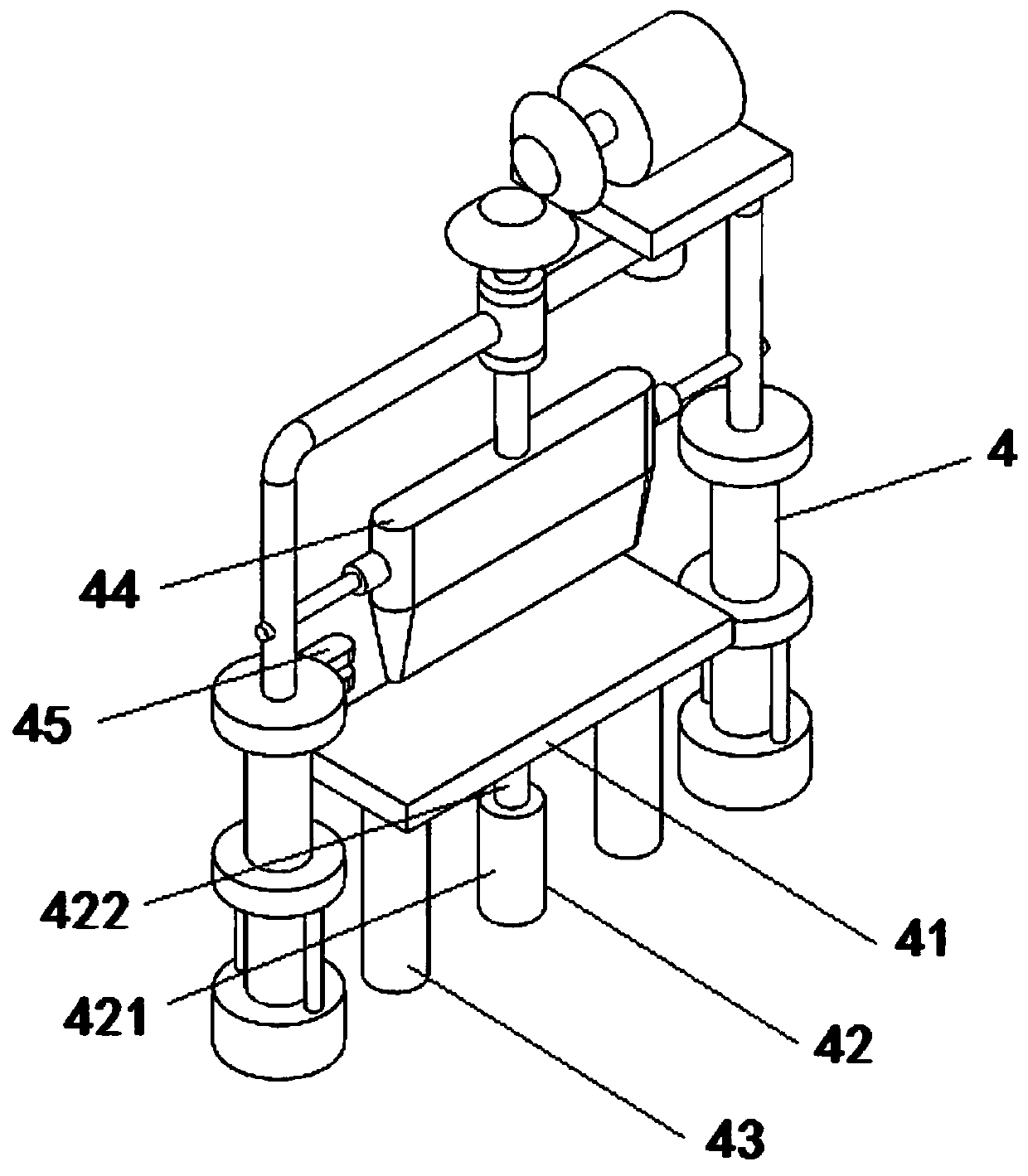
The invention discloses a cutting device for spinning. The cutting device is characterized by comprising a mounting bottom plate and a cutting device body fixedly mounted on the top surface of the mounting bottom plate, wherein the cutting device body comprises a textile winding mechanism, a cutting mechanism and a cut product placing mechanism which are sequentially arranged from left to right. According to the cutting device, through arrangement of the cutting mechanism, lifting of a cutter head is controlled to lift through a second hydraulic rod, cutting of textile fabric is completed, theworking efficiency is improved, through arrangement of the textile winding mechanism, the cutting mechanism and the cut product placing mechanism which are sequentially set, the whole set of cuttingdevice is provided, and the cutting efficiency of the textile fabric is guaranteed.

Description

technical field [0001] The invention belongs to the technical field of textile equipment, and particularly relates to a textile cutting equipment. Background technique [0002] In the processing of textile fabrics, the fibers are generally woven into yarns, woven into grey fabrics, and then refined and bleached into refined and bleached fabrics, which are dyed and finished to obtain dyed fabrics. [0003] In the actual production process, sometimes the textiles need to be cut, and the existing cutting device needs to manually control the movement of the cutting head to complete the cutting of the textiles, and the work efficiency is low. SUMMARY OF THE INVENTION [0004] The purpose of the present invention is to overcome the above problems existing in the prior art, and to provide a cutting device for textiles. Through the setting of the cutting mechanism and the lifting and lowering of the cutting head controlled by the second hydraulic rod, the cutting of textile fabric...

Claims


Application Information

Patent Timeline
Patent Type & Authority Applications(China)
IPC IPC(8): B26D1/08B26D5/12B26D7/26B26D7/02B26D7/06B26D7/32D06H7/02
CPCB26D1/085B26D5/12B26D7/025B26D7/06B26D7/2628B26D7/32B26D2007/322B26F2210/12D06H7/02
Inventor 王灼义
Owner 临沂协润工贸有限公司
Learn More