Cab front suspension structure and automobile
A technology of cab front suspension and lifting mechanism, which is applied to the upper structure, upper structure of trucks, vehicle components, etc., can solve problems such as fatigue damage and instability in the turning process, so as to reduce fatigue damage and improve turning Stability, the effect of improving stability
- Summary
- Abstract
- Description
- Claims
- Application Information
AI Technical Summary
Problems solved by technology
Method used
Image
Examples
Embodiment 1
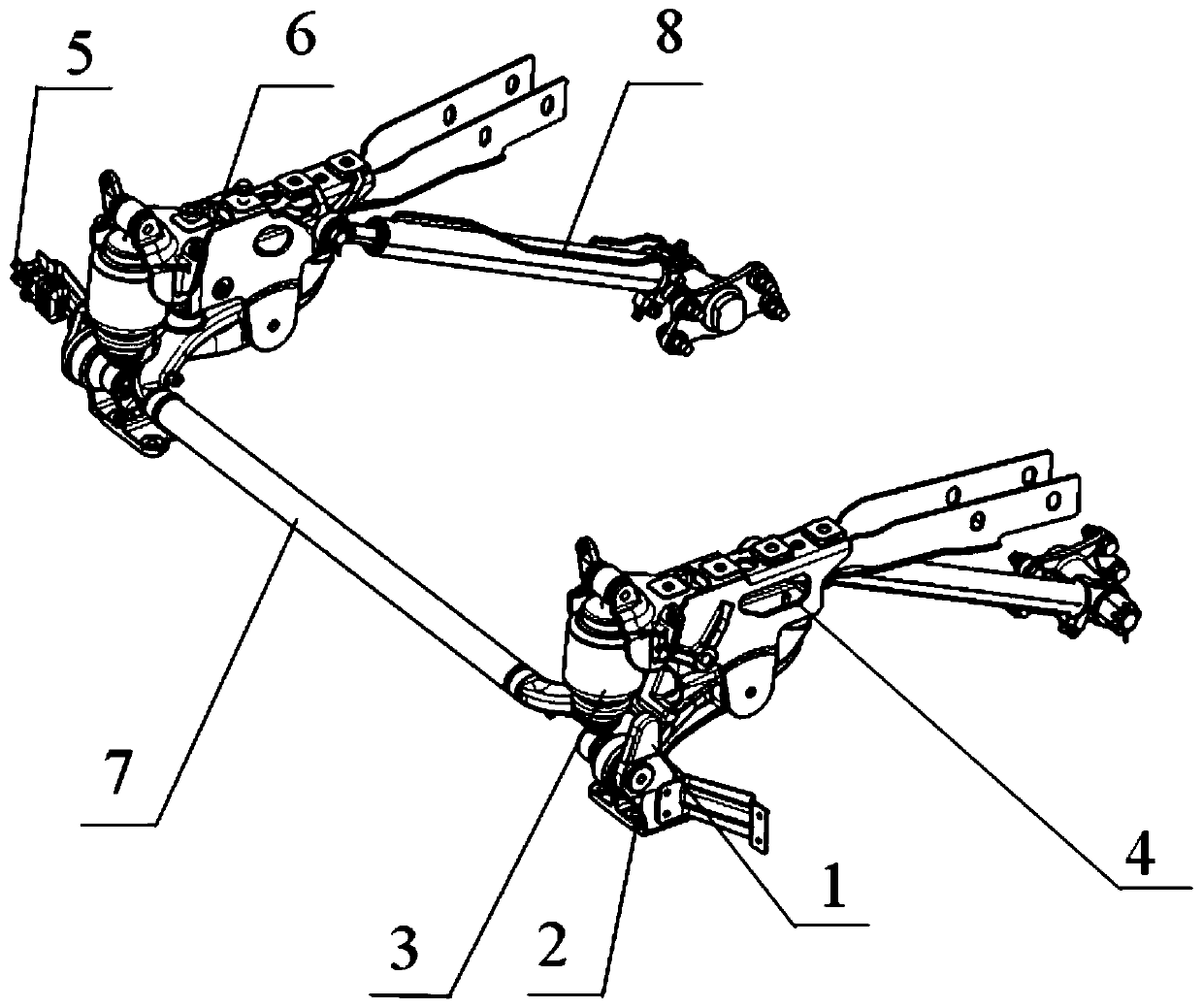
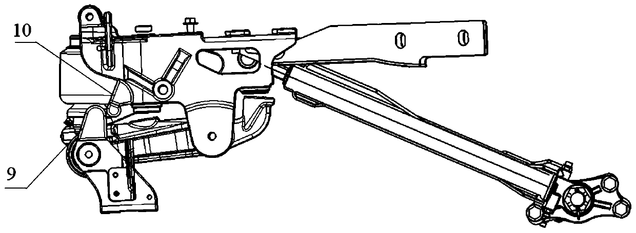
[0029] refer to Figure 1-Figure 4 As shown, the present embodiment is a cab front suspension structure, including a stabilizer bar assembly, a shock absorber assembly, an upper bracket assembly, a lower bracket assembly and a lifting mechanism, including a stabilizer bar 7, Shock absorber (air spring) 3, upper bracket 4, lower bracket 1 and lift cylinder 8; one end of upper bracket 4 is connected to the upper end of shock absorber 3, and the other end is rotatably connected to the lifting mechanism (lift cylinder); upper bracket 4 has Corresponding to the first position and the second position of the driving state and the overturning state respectively;
[0030] The lower bracket assembly also includes an overturning shaft 2 and an overturning guide rail 9. The overturning guide rail 9 is fixedly arranged on the upper part of the lower bracket assembly. The upper part of the overturning guide rail 9 is provided with an arc-shaped guide rail surface. The lower end of the shoc...
Embodiment 1-1
[0033] Based on Example 1, in this example, refer to figure 1 with figure 2 As shown, the shock absorber 3 in the shock absorber assembly adopts an air spring. The lower end of the shock absorber is fixedly connected with the turning shaft 2, and the middle part of the upper bracket assembly is connected with the turning shaft 2 through the stabilizer bar assembly. Since the turning shaft is fixedly arranged at both ends of the stabilizer bar, the lower end of the shock absorber 3 and the upper bracket assembly can also be connected to the stabilizer bar assembly.
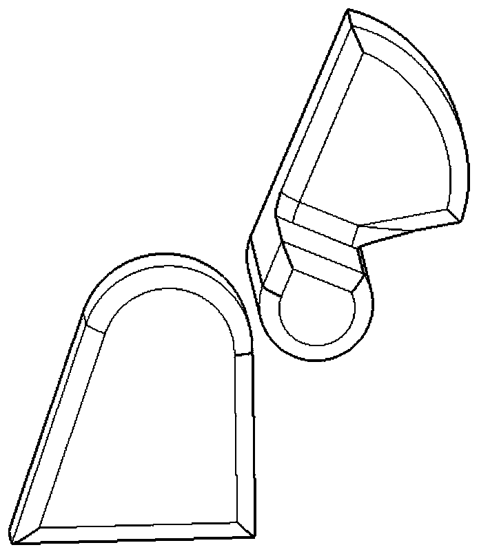
[0034] The turning guide rail 9 is integrally formed with the lower bracket. The overturning roller 10 is fixedly connected to the upper bracket 4 through an integrally formed mounting plate, and the position where the overturning roller can contact the guide rail surface is an open ring with a wall thickness of 90mm, and the two ends of the opening are integrally connected with L-shaped reinforcing ribs.
[00...
Embodiment 2
[0047] This embodiment is a car, which includes a cab and a front suspension structure of the cab. The front suspension structure of the cab adopts the implementation methods in Example 1, and the cab is installed on the upper bracket assembly in the front suspension structure. superior.
PUM
 Abstract
Description
Claims
Application Information
 - R&D
- Intellectual Property
- Life Sciences
- Materials
- Tech Scout
- Unparalleled Data Quality
- Higher Quality Content
- 60% Fewer Hallucinations
Browse by: Latest US Patents, China's latest patents, Technical Efficacy Thesaurus, Application Domain, Technology Topic, Popular Technical Reports.
© 2025 PatSnap. All rights reserved.Legal|Privacy policy|Modern Slavery Act Transparency Statement|Sitemap|About US| Contact US: help@patsnap.com


