Intelligent carbon sliding plate clamping mechanism with wear resistance function and using method thereof
A clamping mechanism and carbon sliding plate technology, applied in the direction of preventing mechanical damage to containers, containers, internal accessories, etc., can solve the problems of impact damage of support columns and bearing platforms, inconvenient clamping thickness of carbon sliding plates, poor stability of carbon sliding plates, etc. , to achieve the effect of reducing impact force, increasing stability and high stability
- Summary
- Abstract
- Description
- Claims
- Application Information
AI Technical Summary
Problems solved by technology
Method used
Image

Examples
Embodiment 1
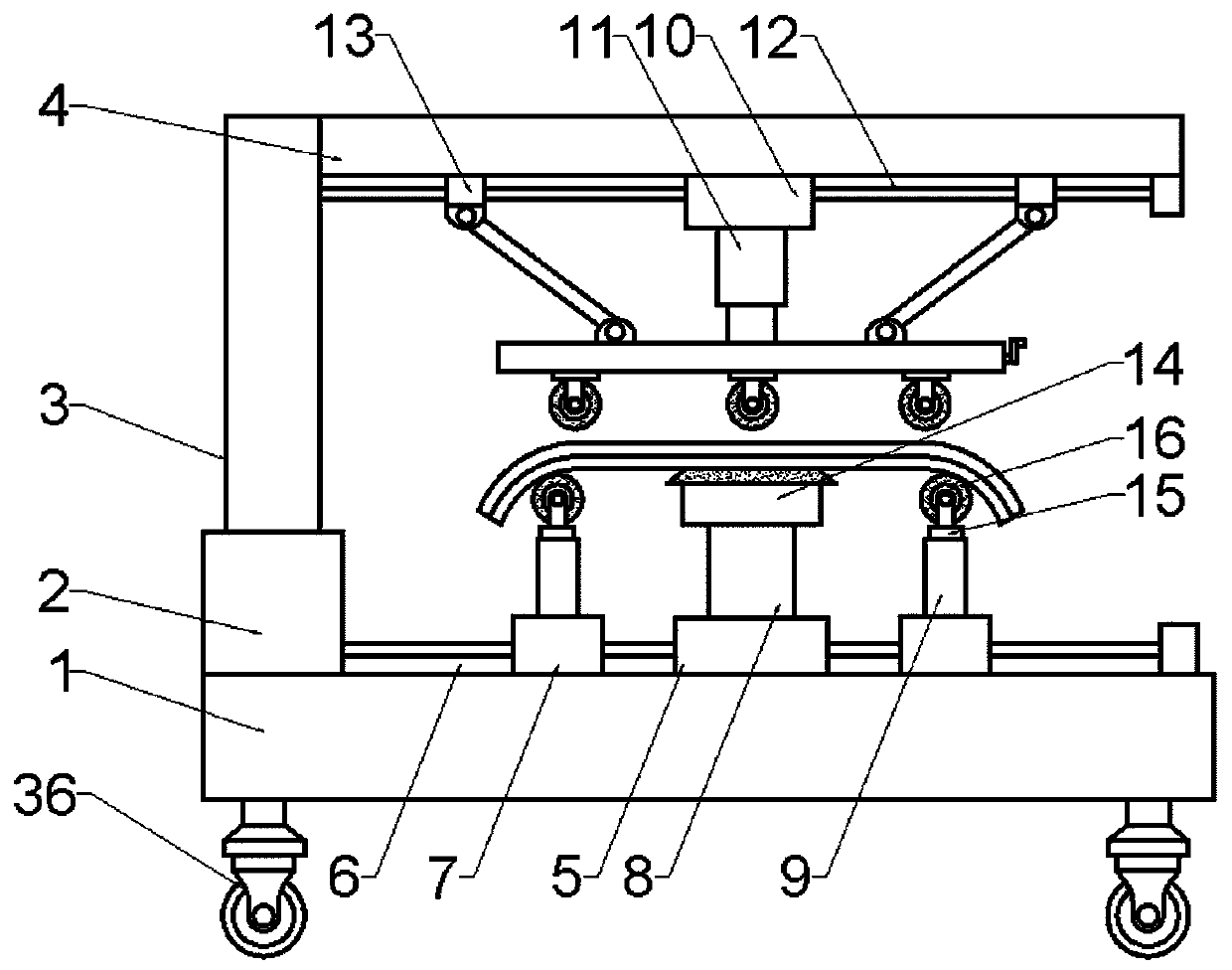
[0028] Embodiment 1: see Figure 1-5, an intelligent carbon slide clamping mechanism with a wear-resistant function, including a base plate 1, the base plate 1 is a horizontally arranged rectangular plate, and a rectangular fixing seat 2 is fixedly installed in the middle of one side of the top surface of the base plate 1, A vertical column 3 is fixedly installed in the middle of the top surface of the fixed seat 2, and a horizontal beam 4 is fixedly connected to the top of the inner column of the column 3, and the column 3 and the beam 4 are rectangular columns. In the middle part of the top surface of the base plate 1, a rectangular bearing seat 5 is fixedly installed, and the top surface of the base plate 1 on both sides of the bearing base 5 is horizontally fixed with a T-shaped slideway 6, and each T-shaped slideway On the track 6, a sliding block 7 is movable, and the bottom surface of each sliding block 7 is provided with a T-shaped chute in cooperation with the T-shape...
Embodiment 2
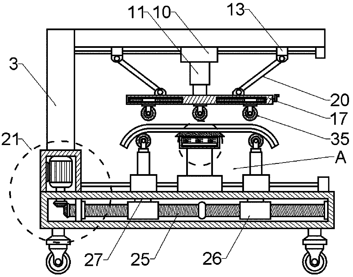
[0034] Example 2: see Figure 6 , in this embodiment, the present invention also proposes a method for using an intelligent carbon slide clamping mechanism with wear-resistant function, including the following steps:
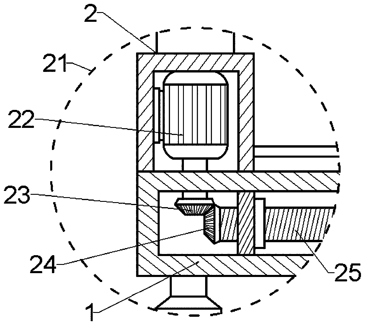
[0035] Step 1: Firstly, the cylinder 11 and the motor 22 are electrically connected to the external power supply through wires, and the staff places the carbon slide plate on the top of the wear-resistant layer 34 above the bearing platform 14, and then adjusts it according to the length of the carbon slide plate;
[0036] Step 2, drive the active bevel gear 23 to rotate by controlling the rotation of the motor 22, drive the threaded rod 25 to rotate through the meshing transmission of the active bevel gear and the passive bevel gear 24, and drive the first threaded sleeve 26 to be opposite on the rod body through the rotation of the threaded rod 25 To move, through the movement adjustment of the first threaded sleeve 26 on the rod body to drive the connecting p...
PUM
 Abstract
Description
Claims
Application Information