Four-way type unloading device for belt conveyor

A technology of belt conveyor and unloading device, which is applied in the direction of transportation, packaging, loading/unloading, etc. It can solve the problems of incomplete unloading of the unloader, reduced service life of the conveyor belt, and wear of the conveyor belt to avoid wear and tear Conveyor belt, solve the effect of high height and clean unloading site

Pending Publication Date: 2020-06-05
COFCO ENG MAOSHENG EQUIP (HENAN) CO LTD +2
View PDF0 Cites 0 Cited by
  • Summary
  • Abstract
  • Description
  • Claims
  • Application Information

AI Technical Summary

Problems solved by technology

[0003] (1) The conveyor belt in the belt conveyor is generally a concave structure with a low middle and high sides. The eight-shaped unloading plate of the plow unloader cannot completely contact the top surface of the conveyor belt, and the bottom surface of the unloading plate is in contact with the conveyor belt. There is a certain gap between the top surfaces, and the material will pass through the gap, resulting in incomplete discharge of the unloader and serious material leakage
[0004] (2) The bottom surface of the unloading plate is in contact with the top surface of the conveyor belt, which will wear the conveyor belt, resulting in a significant decrease in the service life of the conveyor belt and increasing the cost of material transportation
[0005] (3) The existing plow unloader lacks necessary dust and ash collection devices, resulting in a very harsh unloading site environment and serious pollution
[0006] (4) When the existing plow unloader is unloading, the existing materials on the conveyor must be transported before the eight-shaped unloading plate of the unloader can be dropped. Otherwise, the unloading plate will fall, and the material on the conveyor belt will The material is sandwiched between the bottom surface of the unloading plate and the top surface of the conveyor belt, and the leakage phenomenon will be more serious
Therefore, the existing plow unloader cannot realize the random switching of the belt material

Method used


Image

  • Four-way type unloading device for belt conveyor
  • Four-way type unloading device for belt conveyor
  • Four-way type unloading device for belt conveyor

Examples


Embodiment Construction

[0034] The present invention will be further described in detail below in conjunction with the accompanying drawings.

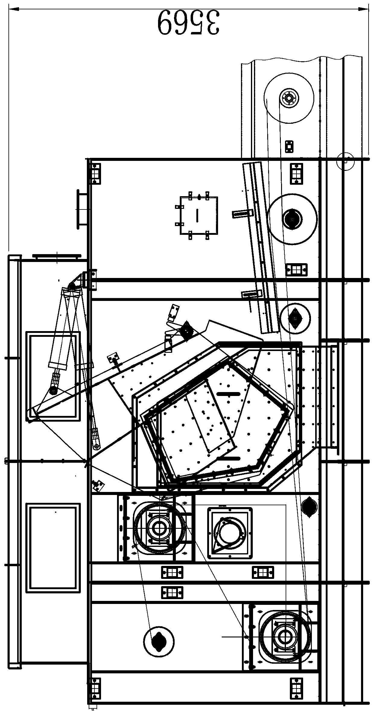
[0035] Such as Figure 5~11 As shown, a four-way unloading device for a belt conveyor includes a conveyor belt 1, a rising drum 2, a falling drum 3, a casing 4, a discharge hopper 5, a power unit 8 and a discharge box 6, and the The casing 4 is provided with a rising roller 2 and a falling roller 3, the rising roller 2 and the falling roller 3 are connected by the conveyor belt 1, the rising roller 2 and the falling roller 3 make the conveyor belt 1 form a drop, the lifting roller 2 It is located at the discharge end of the high-level conveyor belt 1, and the fall-back roller 3 is located at the starting end of the low-level conveyor belt 1. The casing 4 is provided with a discharge hopper 5, and the discharge hopper 5 is tightly connected to the casing 4. The described The unloading hopper 5 includes a housing 501, a feeding hopper 508, a material throwing ...


PUM


Abstract

The invention provides a four-way type unloading device for a belt conveyor. An ascending roller and a falling roller are arranged on an unloading section of the belt conveyor, so that a conveying belt has a fall, and then an unloading hopper is arranged at the fall; two feeding channels are arranged at the upper part of the unloading hopper, a material throwing channel and two unloading channelsare arranged at the lower part of the unloading hopper, and the two unloading channels are arranged on the two sides of the material throwing channel; and an unloading device capable of being overturned is arranged in the unloading hopper. According to the four-way type unloading device, the unloading channel and the material throwing channel are switched through overturning of the unloading device, so that the belt material of unloading and material throwing of the belt conveyor can be switched at will; the unloading hopper is not in contact with the conveying belt, so that the conveying beltis prevented from being abraded; and the material leakage phenomenon cannot be generated in the unloading and material throwing processes, the overall height is low, and the defects of a plough typeunloading device and a material throwing distribution unloading device can be effectively overcome.

Description

Technical field: [0001] The invention belongs to the technical field of grain conveying machinery and equipment, and in particular relates to a four-way unloading device for a belt conveyor. Background technique: [0002] The unloader is a mechanical device used to perform multi-point unloading and control the flow of materials on the conveyor. At present, in the field of grain transportation, most unloaders for belt conveyors are plow unloaders, such as figure 1 , figure 2 As shown, the plow unloader is arranged on the frame of the belt conveyor, and its main unloading mechanism is a figure-eight unloading plate 201 with a cross-section that can move up and down. When unloading is required, the unloading The plate 201 moves downward, and the bottom plate of the unloading plate 201 is close to the top surface of the conveyor belt 200. Under the blocking action of the splayed unloading plate 201, the material is unloaded along the splayed unloading plate 201 to both sides o...

Claims


Application Information

Patent Timeline
Patent Type & Authority Applications(China)
IPC IPC(8): B65G65/42
CPCB65G65/42
Inventor 原富林黄灿赵江伟王斌兴荆海伟徐川川项文霞孟青青魏克娴
Owner COFCO ENG MAOSHENG EQUIP (HENAN) CO LTD
Why Eureka
Try Eureka