Cloth roll shaft height adjustable cloth blocking plate structure of spreading machine cloth feeding cradle

A cloth stretching machine and cloth roll technology, which is applied in the field of clothing machinery, can solve problems such as the inability to support the cloth roll and the inability to adjust the size and adaptability of the diameter of the cloth roll, so as to achieve the effect of avoiding left and right movement and good adaptability

Pending Publication Date: 2020-06-05
苏州比阳特服装设备有限公司
View PDF15 Cites 2 Cited by
  • Summary
  • Abstract
  • Description
  • Claims
  • Application Information

AI Technical Summary

Problems solved by technology

However, because the baffle assembly given in this patent only plays a role in limiting the ends of the cloth roll, it can ne

Method used


Image

  • Cloth roll shaft height adjustable cloth blocking plate structure of spreading machine cloth feeding cradle
  • Cloth roll shaft height adjustable cloth blocking plate structure of spreading machine cloth feeding cradle
  • Cloth roll shaft height adjustable cloth blocking plate structure of spreading machine cloth feeding cradle

Examples


Example Embodiment

[0023] In order to be able to understand the technical essence and beneficial effects of the present invention more clearly, the applicant will describe in detail in the form of examples below, but the description of the examples is not a limitation to the solution of the present invention. Anything made according to the concept of the present invention All equivalent transformations that are merely formal rather than substantive should be regarded as the scope of the technical solution of the present invention.
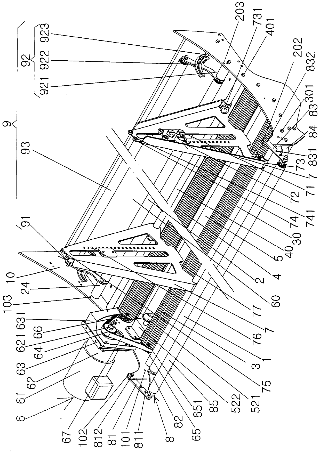
[0024] In the following description, all concepts related to the directionality of up, down, left, right, front and back, or orientation, are all based on figure 1 The position state shown is for the purpose, so it cannot be understood as a special limitation to the technical solution provided by the present invention.

[0025] See figure 1 , Shows the cradle left wall panel 10, the cradle right wall panel 20, the front baffle roll 1, the rear baffle roll 2, the first dr...


PUM


Abstract

The invention disclose a cloth roll shaft height adjustable cloth blocking plate structure of a spreading machine cloth feeding cradle. The spreading machine cloth feeding cradle comprises a cradle left wall plate, a cradle right wall plate, a cloth roll front blocking roller, a cloth roll rear blocking roller, a cloth roll first driving roller, a cloth roll second driving roller, a cloth roll auxiliary driving roller and a driving roller driving mechanism. The cloth roll front blocking roller is mounted between front ends of the cradle left and right wall plates, the cloth roll rear blockingroller is mounted between rear ends of the cradle left and right wall plates, the cloth roll first and second driving rollers are mounted between the middles of the cradle left and right wall plates,the cloth roll auxiliary driving roller is mounted between the cradle left and right wall plates, the driving roller driving mechanism is mounted on the cradle left wall plate, and the cloth roll shaft height adjustable cloth blocking plate structure comprises a pair of cloth roll baffle bodies, a cloth roll baffle front bearing rod and a cloth roll baffle rear bearing rod. The structure has the advantages that the middles of the pair of the cloth roll baffle bodies are longitudinally provided with cloth roll shaft upper and lower adjusting grooves, and cloth roll shaft bearing mechanisms aremounted on the positions corresponding to the cloth roll shaft upper and lower adjusting grooves. Left and right moving is avoided, manual lifting of a cloth roll is not needed, and the structure hasthe good adaptation to cloth rolls with the different sizes and diameters.

Description

technical field [0001] The invention belongs to the technical field of clothing machinery, and in particular relates to a cloth baffle structure with adjustable height of a cloth reel of a cloth feeding cradle of a cloth stretching machine. Background technique [0002] The aforementioned stretching machine is also called "spreading machine", or even "spreading machine". The function of the pulling device is to clamp and pull the head of the cloth to the working table, that is, the spreading table, for cutting by the cloth cutting device of the pulling machine. The cloth feeding device of the spreading machine is the cloth feeding cradle of the aforementioned spreading machine. [0003] There is no lack of technical information related to stretching machines in the published Chinese patent documents, such as CN202988390U (a knitted cloth machine), CN103342251B (a stretching machine with a manipulator clamping mechanism), CN104876053A (a automatic spreading machine), CN1049...

Claims


Application Information

Patent Timeline
IPC IPC(8): B65H47/00B65H16/00B65H16/06
CPCB65H16/00B65H16/06B65H47/00B65H2701/174
Inventor 徐建新
Owner 苏州比阳特服装设备有限公司
Why Eureka
Try Eureka