Mechanical-based heat treatment device for flanged steel pot products

A technology for heat treatment devices and steel pots, applied in heat treatment furnaces, heat treatment equipment, manufacturing tools, etc., can solve the problems of breakdown in the flanging area, affect product quality, and different distances, and achieve the effect of improving the functional structure

Inactive Publication Date: 2020-06-05
天威英利
View PDF0 Cites 2 Cited by
  • Summary
  • Abstract
  • Description
  • Claims
  • Application Information

AI Technical Summary

Problems solved by technology

[0004] The purpose of the present invention is to provide a heat treatment device based on mechanical processing of steel pan products after flanging, to solve the problem that the existing high-frequency heating rings are mostly fixed and installed on the bluing treatment tooling of steel pan products, steel pan products Due to the different heights and dimensions of the parts, the distance between the flanging area made by the top flanging process and the high-frequency heating ring is not the same. Therefore, when it is heated by the high-frequency heating ring at high temperature, it will cause breakdown in the flanging area. Problems affecting product quality

Method used


Image

  • Mechanical-based heat treatment device for flanged steel pot products
  • Mechanical-based heat treatment device for flanged steel pot products
  • Mechanical-based heat treatment device for flanged steel pot products

Examples


Embodiment Construction

[0025] The following will clearly and completely describe the technical solutions in the embodiments of the present invention with reference to the accompanying drawings in the embodiments of the present invention. Obviously, the described embodiments are only some, not all, embodiments of the present invention.

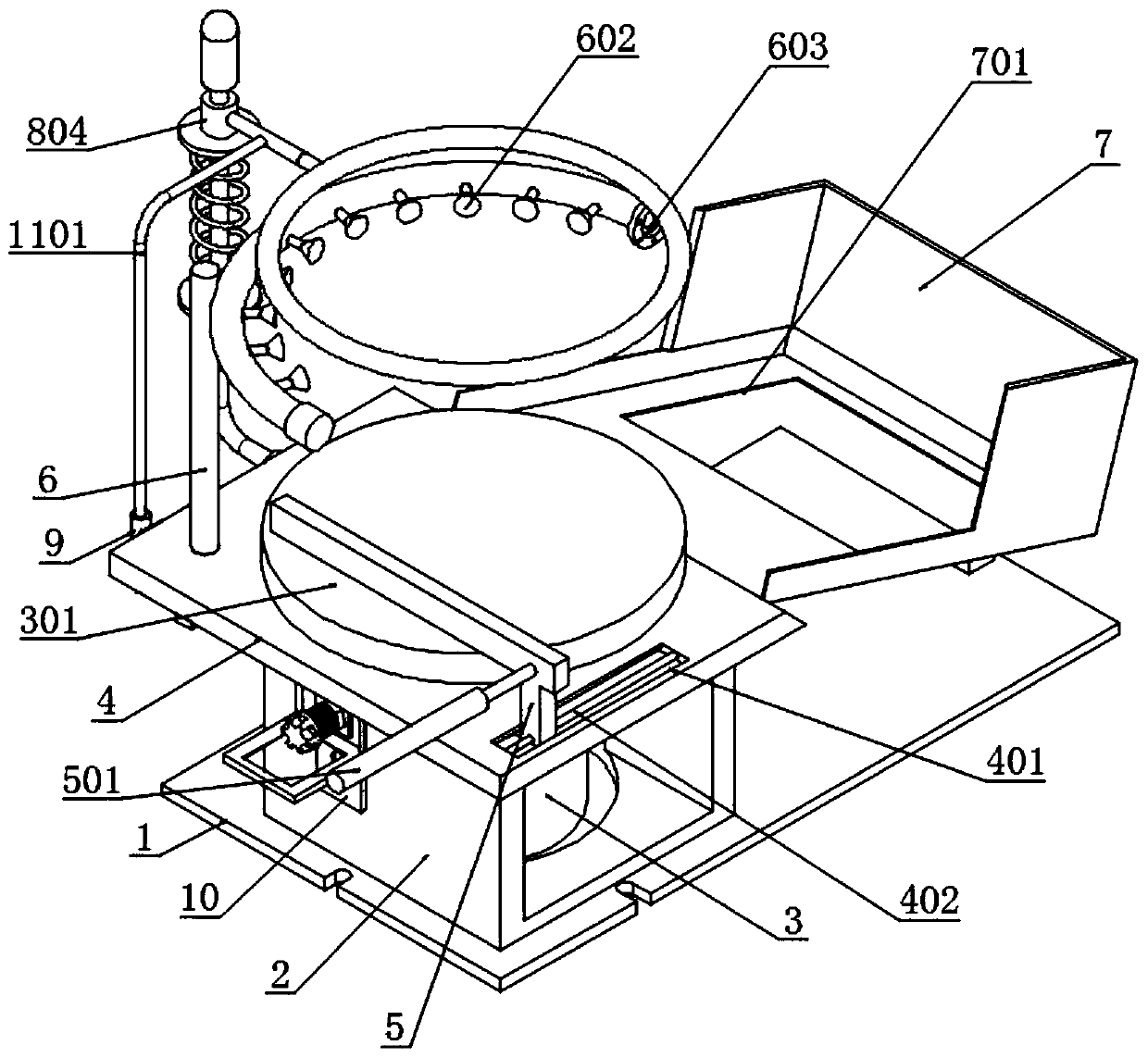
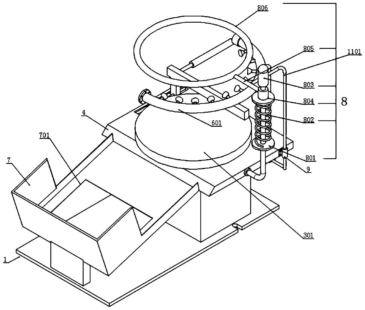
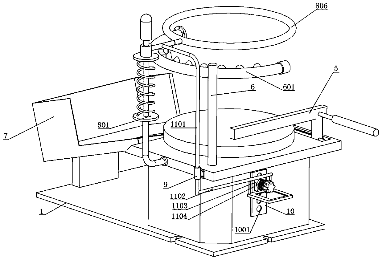
[0026] see Figure 1 to Figure 9 , a kind of embodiment that the present invention provides: based on the heat treatment device of the steel pan product processing flanging of machine, comprise bottom plate 1, regulating plate 10 and pressing mechanism 11; The top surface of the vertical compartment 2 supports the top seat 4 welded with a rectangular plate structure, and a sliding material seat 7 is installed on the right side of the top surface of the bottom plate 1 through a vertical welding plate; the front side of the vertical compartment 2 is provided with a rectangular storage chamber , a slow motor 3 is installed in its storage cavity, the rotation axis of the...


PUM


Abstract

The invention discloses a mechanical-based heat treatment device for flanged steel pot products, and relates to the technical field of auxiliary tool structures. The problem that breakdown of existingsteel pot products is caused when the existing steel pot products are blued by a high-frequency heating ring is solved, the device comprises a bottom plate, an adjusting plate and a treading and pressing mechanism, wherein a vertical cabin is installed on the left side of the top surface of the bottom plate, a top base with a rectangular plate structure is further supported and welded on the topsurface of the vertical cabin, a rectangular storage cavity is formed in the front side of the vertical cabin, a low-speed motor is installed in the storage cavity of the vertical cabin, the axial direction of the low-speed motor extends upwards from the top position of the top base, a discoid rotating plate is installed on a motor shaft of the low-speed motor, and a stand column is vertically welded to the left rear side of the top surface of the top base. By means of the mechanism, polluted smoke generated in a bluing process can be discharged outwards to the maximum extent, the environment-friendly structural characteristic is achieved, a pushing and pressing type discharging mechanism is further arranged, a steel pot falling on the rotating plate can be discharged towards one side, andthe functional structure is further improved.

Description

technical field [0001] The invention relates to the technical field of auxiliary tooling structures, in particular to a mechanically-based heat treatment device for steel pan products after flanging. Background technique [0002] After the steel pot is punched, the top needs to be flanged. In order to improve the strength of the top flanging area, when the product is in use, the top flanging area is not easy to be deformed by force, so it is necessary to use a high-frequency heating ring on the top. Blue heat treatment in the flanging area, through bluing heat treatment, change the organizational structure of the top flanging area to improve product quality. [0003] Most of the existing high-frequency heating rings are installed in a fixed way on the tooling of the blued steel pan product. Due to the different heights and dimensions of the steel pan product, the flange area made by the top flanging process is far away from the high-frequency heating The distance between th...

Claims


Application Information

Patent Timeline
Patent Type & Authority Applications(China)
IPC IPC(8): C21D1/42C21D9/00B08B15/04
CPCB08B15/04C21D1/42C21D9/0068Y02P10/25
Inventor 李颖
Owner 天威英利
Why Eureka
Try Eureka