Bead embroidery device for embroidery machine

An embroidery machine and bead technology, applied in the field of embroidery machines and embroidery machines, can solve the problems of complex mechanical structure, easy occurrence of leaking beads, easy occurrence of mechanical failures, etc., and achieves the effect of reducing use cost and improving production efficiency.

Active Publication Date: 2020-06-05
丹阳德顺刺绣机械有限公司
View PDF9 Cites 1 Cited by
  • Summary
  • Abstract
  • Description
  • Claims
  • Application Information

AI Technical Summary

Problems solved by technology

[0002] At present, the domestic bead embroidery device, when embroidering beads of different specifications, is prone to bead leakage when switching between beads of different specifications during embroidery. The mechanical structure is complex and prone to mechanical failure during switching, and the production cost is high.

Method used


Image

  • Bead embroidery device for embroidery machine
  • Bead embroidery device for embroidery machine
  • Bead embroidery device for embroidery machine

Examples


Embodiment Construction

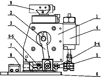
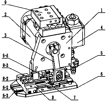
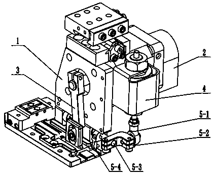
[0029] Depend on Figure 1 to Figure 14 Known, a schematic diagram of a bead embroidery device for an embroidery machine, including a base plate assembly 1, a first drive assembly 2, a swing arm 3, a second drive assembly 4, a switch assembly 5, a base 6, a feeding assembly 7, and a material distribution assembly 8. The above-mentioned first driving assembly 2 is installed on the back of the substrate assembly 1, the swing arm 3 is connected to the first driving assembly 2, the second driving assembly 4 is fixed on the side of the substrate assembly 1, and the switching assembly 5 is connected to the second driving assembly 4 , the base 6 is fixed on the bottom of the substrate assembly 1, the feeding assembly 7 is mounted on the chute 6-2 of the base 6, the front end of the swing arm 3 is assembled and connected with the feeding assembly 7, and the swing arm 3 is mounted on the first driving assembly 2 Under the effect of swinging left and right, the feeding assembly 7 is dri...


PUM


Abstract

Disclosed is a bead embroidery device for an embroidery machine. A first driving assembly (2) is mounted on the back of a base plate assembly (1); a swing arm (3) is connected with the first driving assembly (2); a second driving assembly (4) is fixed on the side of the base plate assembly (1); a switching assembly (5) is connected with the second driving assembly (4); a base (6) is fixed at the bottom of the base plate assembly (1); a feeding assembly (7) is mounted on a sliding groove (6-2) of the base (6) in a matched mode; the front end of the swing arm (3) is assembled and connected withthe feeding assembly (7) in a matched mode; and a material separating assembly (8) is mounted on the base (6) in a transverse span mode. According to the bead embroidery device, two single clamp headsare combined into a material separating clamp head, and the cross section of an inner cavity in the combined material separating clamp head is of a quadrilateral structure, so that feeding of beads of multiple diameters can be applicable, and the operation of frequently changing the material separating clamp heads due to different diameters of beads can be omitted, thereby greatly improving the production efficiency and lowering the use cost.

Description

technical field [0001] The invention relates to embroidery machines and the technical field of embroidery machines, in particular to a bead embroidery device for embroidery machines. Background technique [0002] At the present stage, the bead embroidery devices in China are prone to bead leakage when switching between beads of different specifications when embroidering beads of different specifications. When switching, due to the complicated mechanical structure, mechanical failures are likely to occur, and the production cost is high. Contents of the invention [0003] In view of the above-mentioned defects, the purpose of the present invention is to provide a bead embroidery device for embroidery machines, which pushes the beads on two relatively independent distribution chucks respectively by the feeding assembly moving back and forth on the chute of the base, so as to realize fast The purpose of accurately feeding the beads. [0004] The technical solution adopted by...

Claims


Application Information

Patent Timeline
Patent Type & Authority Applications(China)
IPC IPC(8): D05C7/08D05C13/00
CPCD05C7/08D05C13/00Y02P90/30
Inventor 解建国
Owner 丹阳德顺刺绣机械有限公司
Why Eureka
Try Eureka