
Steel rail grinding trolley

A technology of rail grinding car and grinding trolley, which is applied in the direction of track, laying track, track maintenance, etc., can solve the problems of limited application occasions, poor operation stability, poor grinding quality and effect, etc., to achieve good grinding quality and effect, compression The effect of occupying space, beneficial to the design of the whole vehicle and the layout of the multi-power driving mode

Pending Publication Date: 2020-06-05
ZHUZHOU TIMES ELECTRONICS TECH CO LTD
View PDF0 Cites 1 Cited by
  • Summary
  • Abstract
  • Description
  • Claims
  • Application Information

AI Technical Summary

Problems solved by technology

[0008] In view of this, the object of the present invention is to provide a rail grinding trolley to solve the technical problems of limited application occasions, poor running stability, and poor grinding quality and effect of existing subway rail grinding vehicles

Method used


Image

  • Steel rail grinding trolley
  • Steel rail grinding trolley
  • Steel rail grinding trolley

Examples


Embodiment 1

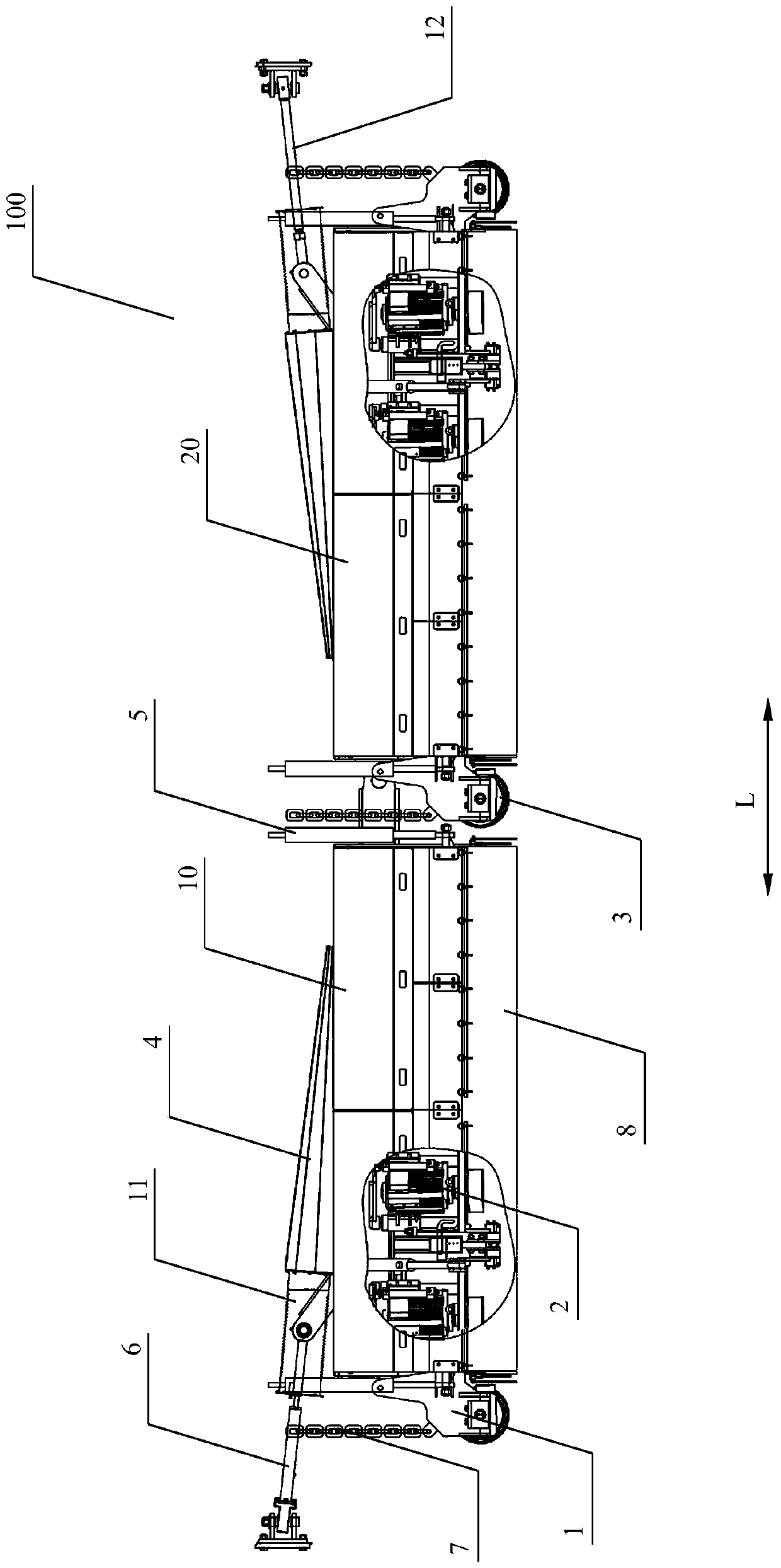
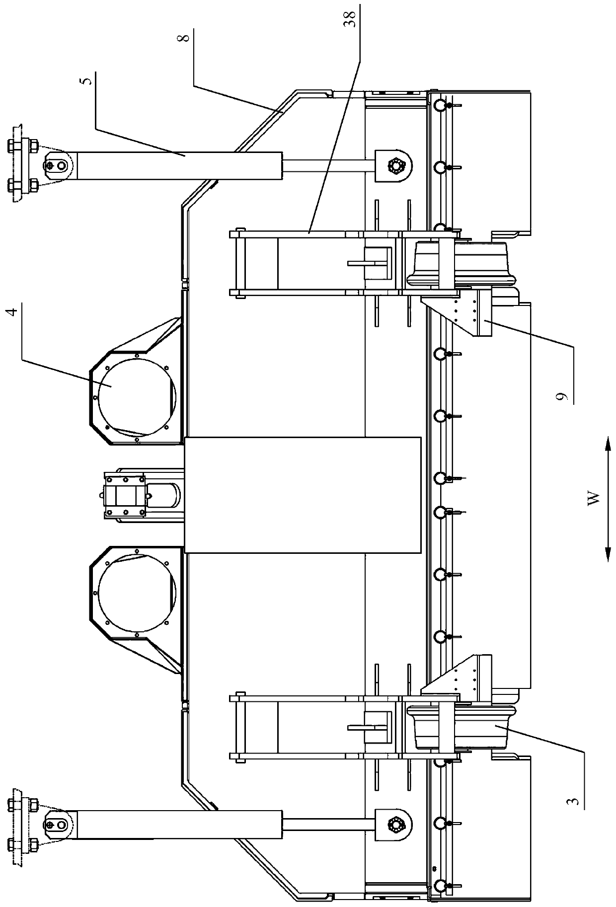
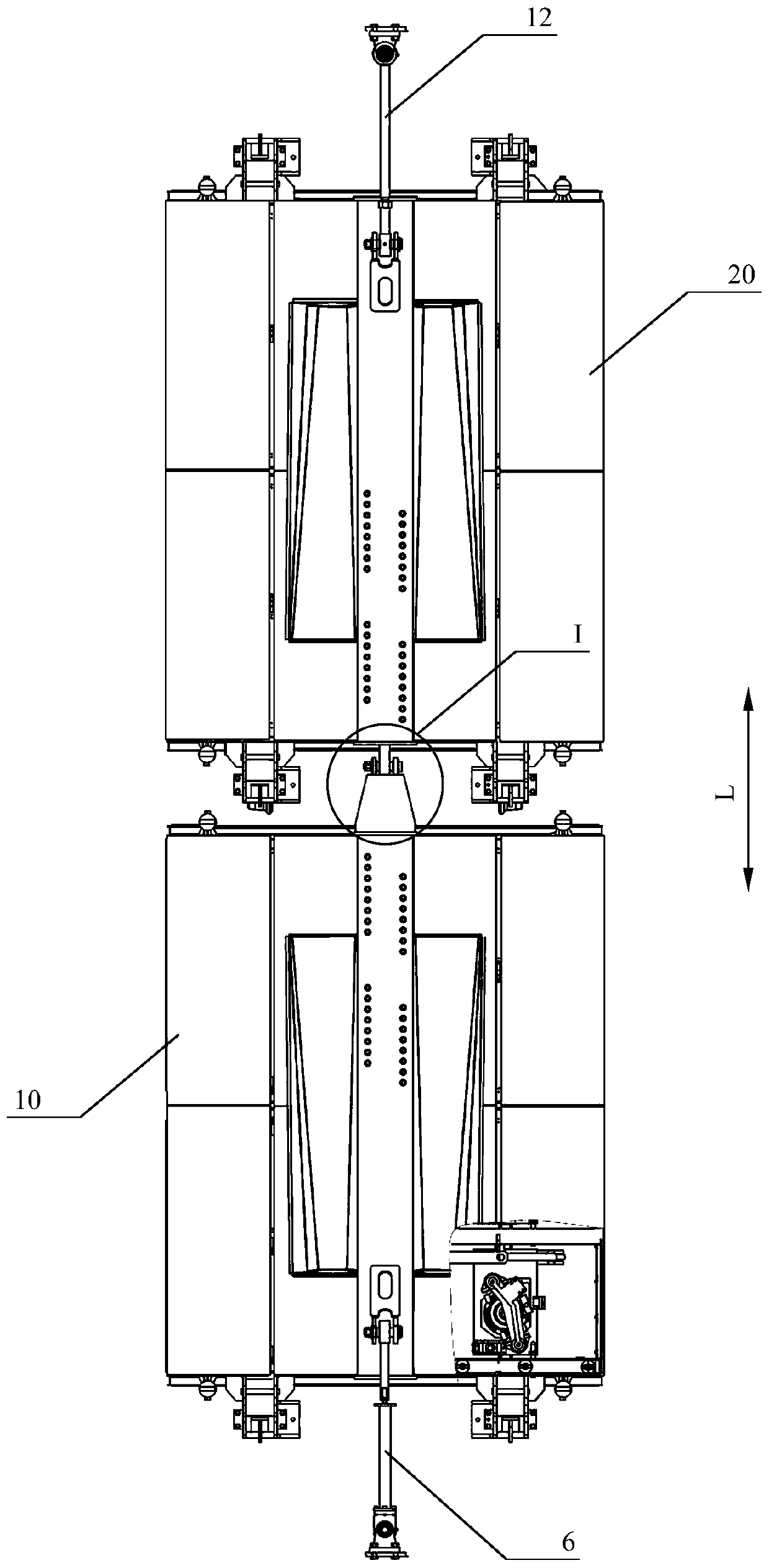
[0047] as attached Figure 7 As shown, an embodiment of a rail grinding trolley 100 is arranged on the lower part of the car body 200 of a subway rail grinding trolley 300. The rail grinding trolley 100 specifically includes: a first grinding trolley 10 and a second grinding trolley 20, the first grinding trolley 10 It is hingedly connected with the second grinding trolley 20. As a typical specific embodiment of the present invention, as attached Figure 4 As shown, the first grinding trolley 10 and the second grinding trolley 20 are hinged through the hinge seat 13 and the hinge joint 14 . The connection between the hinge base 13 and the hinge head 14 is realized by a bolt 15 , and a joint bearing 16 is arranged between the bolt 15 and the hinge head 14 . as attached figure 1 to attach image 3 As shown, the first grinding trolley 10 and the second grinding trolley 20 both include: a vehicle frame 1 , a grinding unit 2 , a running guide wheel 3 , a dust collection channel...

Embodiment 2

[0060] as attached figure 1 And attached Figure 7 As shown, an embodiment of a subway rail grinding car 300 including the rail grinding car 100 described in Embodiment 1 specifically includes: a car body 200 , and a rail grinding car 100 arranged at the lower part of the car body 200 . The rail grinding trolley 100 includes a first grinding trolley 10 and a second grinding trolley 20 hinged to each other. The rail grinding trolley 100 also includes an elastic drawbar 6 and a rigid drawbar 12. The first grinding trolley 10 is connected to the car body 200 through the elastic drawbar 6, and the second grinding trolley 20 is connected to the car body 200 through the rigid drawbar 12. As another typical embodiment of the present invention, the first grinding trolley 10 is connected to the vehicle body 200 through the rigid drawbar 12 , and the second grinding trolley 20 is connected to the vehicle body 200 through the elastic drawbar 6 .

[0061] as attached Figure 8 As shown...


PUM


Abstract

The invention discloses a steel rail grinding trolley. The steel rail grinding trolley comprises two grinding trolleys which are connected in a hinged mode. The grinding trolley comprises a frame, a polishing unit, a walking guide wheel, a dust collecting channel and a fireproof and dustproof device. The grinding unit is arranged in the frame, the walking guide wheels are arranged on the lower portion of the frame, and the dust collecting channel is arranged on the upper portion of the frame. The fireproof and dustproof device wraps the frame except the bottom, and a semi-closed structure of the polishing trolley is formed through the fireproof and dustproof device and the dust collecting channel. The steel rail grinding trolley further comprises an elastic traction rod and a rigid traction rod, one grinding trolley is connected with the trolley body through the elastic traction rod, and the other grinding trolley is connected with the trolley body through the rigid traction rod. The steel rail grinding trolley can solve the technical problems that an existing steel rail grinding trolley is limited in application occasion, poor in operation stability and poor in grinding quality and effect.

Description

technical field [0001] The invention relates to the technical field of track engineering machinery, in particular to a rail grinding trolley used in railway engineering maintenance. Background technique [0002] The rail grinding vehicle is a rail engineering vehicle mainly used for grinding the main line of the track. There are special grinding vehicles for the turnout operation, and there are also individual grinding vehicles that can be used for both main line grinding and turnout grinding. However, the existing rail grinding vehicles generally have many technical problems such as low operating efficiency, hidden safety hazards, heavy environmental pollution, poor dust collection effect, and deviation of the operating landing point, which leads to unsatisfactory overall grinding performance. At present, there are mainly the following types of rail grinding vehicles widely used in China: [0003] 1) PGM-48 grinding car. This type of grinding car is composed of three vehi...

Claims


Application Information

Patent Timeline
IPC IPC(8): E01B31/17
CPCE01B31/17
Inventor 王华朱利君李雪辉罗旦杨全
Owner ZHUZHOU TIMES ELECTRONICS TECH CO LTD
Learn More