Electronic lock, lock control system and working method of lock control system
A control system and lock technology, applied in the field of judicial control system, can solve the problems of risk of being attacked, high labor intensity, quick unlocking, etc., and achieve the effect of high unlocking efficiency, high security, and saving labor costs
- Summary
- Abstract
- Description
- Claims
- Application Information
AI Technical Summary
Problems solved by technology
Method used
Image
Examples
Embodiment 1
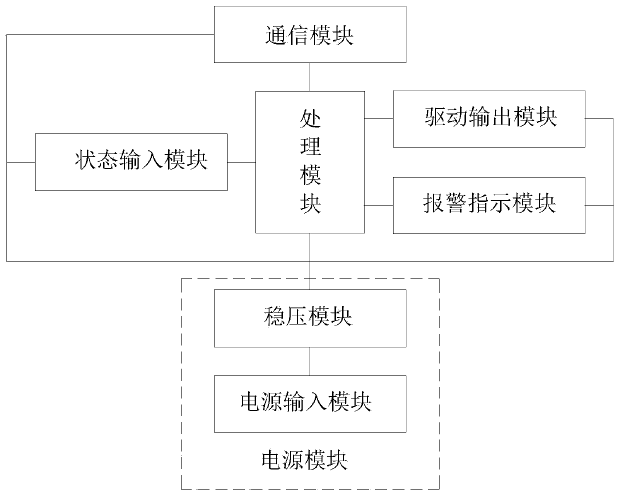
[0048] This embodiment provides an electronic lock, such as figure 1 As shown, it includes a processing module, a state input module, a drive output module, a communication module and a power supply module. The state input module, the drive output module and the communication module are all electrically connected to the processing module. The processing module, the state input module, the drive Both the output module and the communication module are electrically connected to the power module;
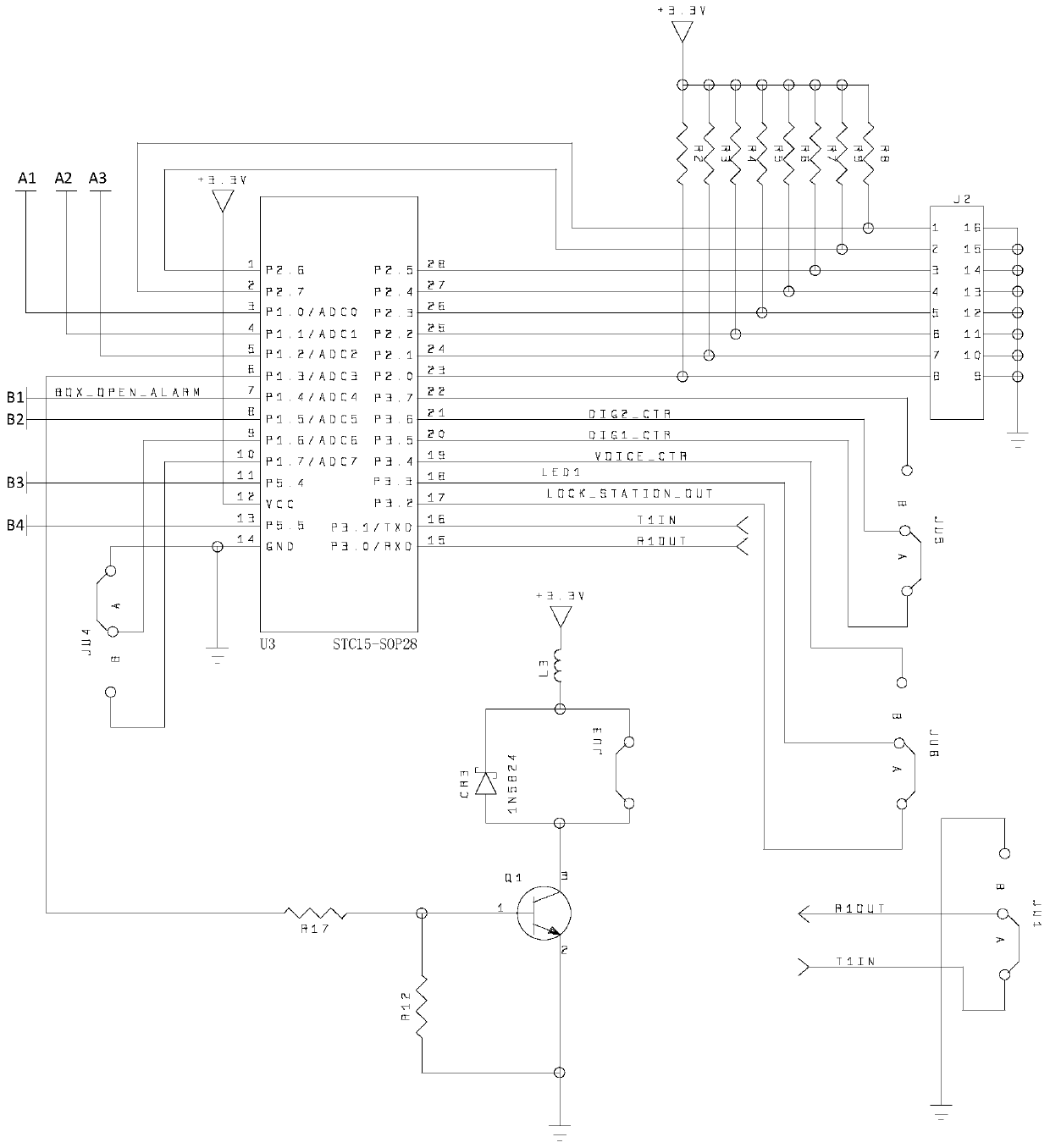
[0049] The processing module, such as figure 2As shown, it is used to receive and process lock cylinder status information and unlock request, and is also used to store and verify operator information and operation logs; in this embodiment, the processor module includes a STC15 series single-chip microcomputer, and the specific model is F2K16S2-28I -SOP28.
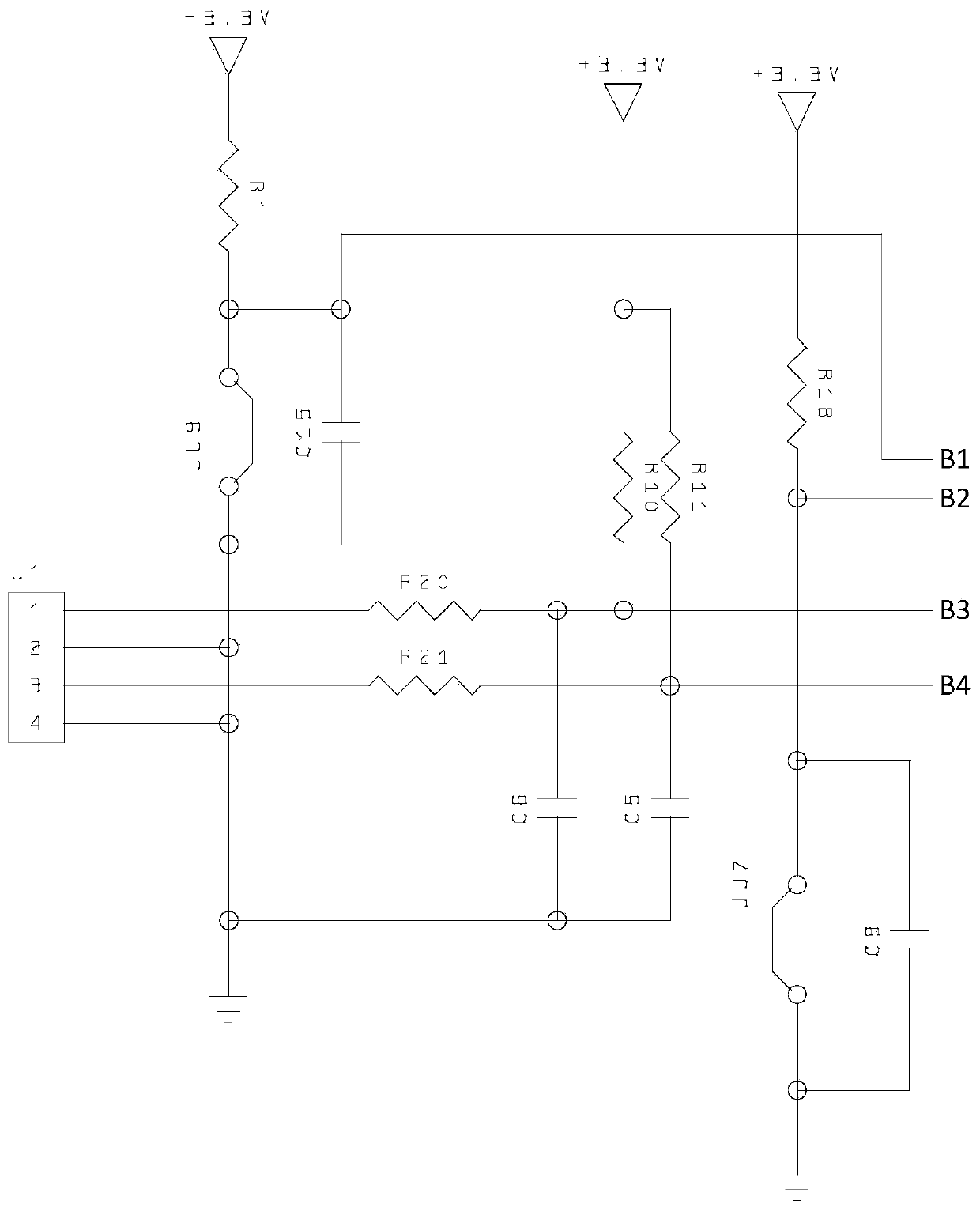
[0050] In this embodiment, the processing module adopts 485 bus design, standard Modbus protocol, stable and reliable performan...
Embodiment 2
[0066] A lock control system, comprising multiple electronic locks according to any one of claims 1 to 4, and further comprising touch sub-consoles respectively communicating with multiple electronic locks, said touch sub-consoles being communicatively connected with a touch master AA;
[0067] The touch master console is used for real-time monitoring of the designated touch sub-control console, and is also used for sending an unlock request to the touch sub-control console;
[0068] The touch sub-console is used for real-time monitoring of the designated electronic lock, and is also used for receiving the unlock request sent by the touch master console and sending the unlock request to the processing module of the corresponding electronic lock.
[0069] Further, the touch sub-console communicates with the touch master console through the TCP / IP protocol.
[0070] In this embodiment, the touch sub-console and the touch master console adopt the TCP / IP network communication pro...
Embodiment 3
[0073] This embodiment discloses a working method based on the lock control system of Embodiment 2, comprising the following steps:
[0074] The processing module sends the lock cylinder status information to the touch control console in real time;
[0075] The touch sub-console receives and displays the lock cylinder status information sent by the processing module in real time, and sends an unlock request to the processing module at a specified time;
[0076] The processing module receives the unlock request sent by the touch sub-console and sends it to the drive output module;
[0077] The drive output module receives the unlock request sent by the processing module, and then controls the opening and closing of the lock cylinder.
[0078] Further, the following steps are also included:
[0079] The touch master console sends an unlock request to the touch sub-console;
[0080] The touch sub-console receives the unlock request sent by the touch master console, and sends i...
PUM
 Abstract
Description
Claims
Application Information
 - R&D
- Intellectual Property
- Life Sciences
- Materials
- Tech Scout
- Unparalleled Data Quality
- Higher Quality Content
- 60% Fewer Hallucinations
Browse by: Latest US Patents, China's latest patents, Technical Efficacy Thesaurus, Application Domain, Technology Topic, Popular Technical Reports.
© 2025 PatSnap. All rights reserved.Legal|Privacy policy|Modern Slavery Act Transparency Statement|Sitemap|About US| Contact US: help@patsnap.com


