Supercharge Your Innovation With Domain-Expert AI Agents!

Fluid slip ring for single-point mooring device

A single-point mooring and fluid technology, which is applied in transportation and packaging, ship parts, anchoring arrangements, etc., can solve the problems of reducing the service life of seals, poor reliability and safety of sealing and rotation, and reducing the service life of slip rings, etc. Achieve the effect of uniform wear, wide application range and long service life

Active Publication Date: 2020-06-05
山东沂南园区开发建设有限公司
View PDF6 Cites 0 Cited by
  • Summary
  • Abstract
  • Description
  • Claims
  • Application Information

AI Technical Summary

Problems solved by technology

[0003] see figure 1 , the communication cavity between the inner and outer rings is sealed by a seal, and the wear and tear of the surface will cause the slip ring to leak, which restricts the service life of the fluid slip ring, and due to the large mass of the offshore engineering ship, the pressure on the slip ring is usually biased to one side , will lead to uneven wear of the seal, further reducing the service life of the seal, and secondly, the vibration caused by the sea waves, and the rotation between the inner and outer rings will reduce the service life of the slip ring
[0004] On the other hand, in some other projects, some high-temperature, high-pressure and high-corrosion media will be transported. For example, in oil exploitation, high-pressure steam will be sent to increase the temperature of the oil to reduce the viscosity of the oil and increase the speed of oil transportation. Large diameter High-pressure fluid slip rings generate large axial force of the medium, and the reliability and safety of sealing and rotation are poor

Method used


Image

  • Fluid slip ring for single-point mooring device
  • Fluid slip ring for single-point mooring device
  • Fluid slip ring for single-point mooring device

Examples


Embodiment Construction

[0023] The following will clearly and completely describe the technical solutions in the embodiments of the present invention with reference to the accompanying drawings in the embodiments of the present invention. Obviously, the described embodiments are only some, not all, embodiments of the present invention. Based on the embodiments of the present invention, all other embodiments obtained by persons of ordinary skill in the art without making creative efforts belong to the protection scope of the present invention.

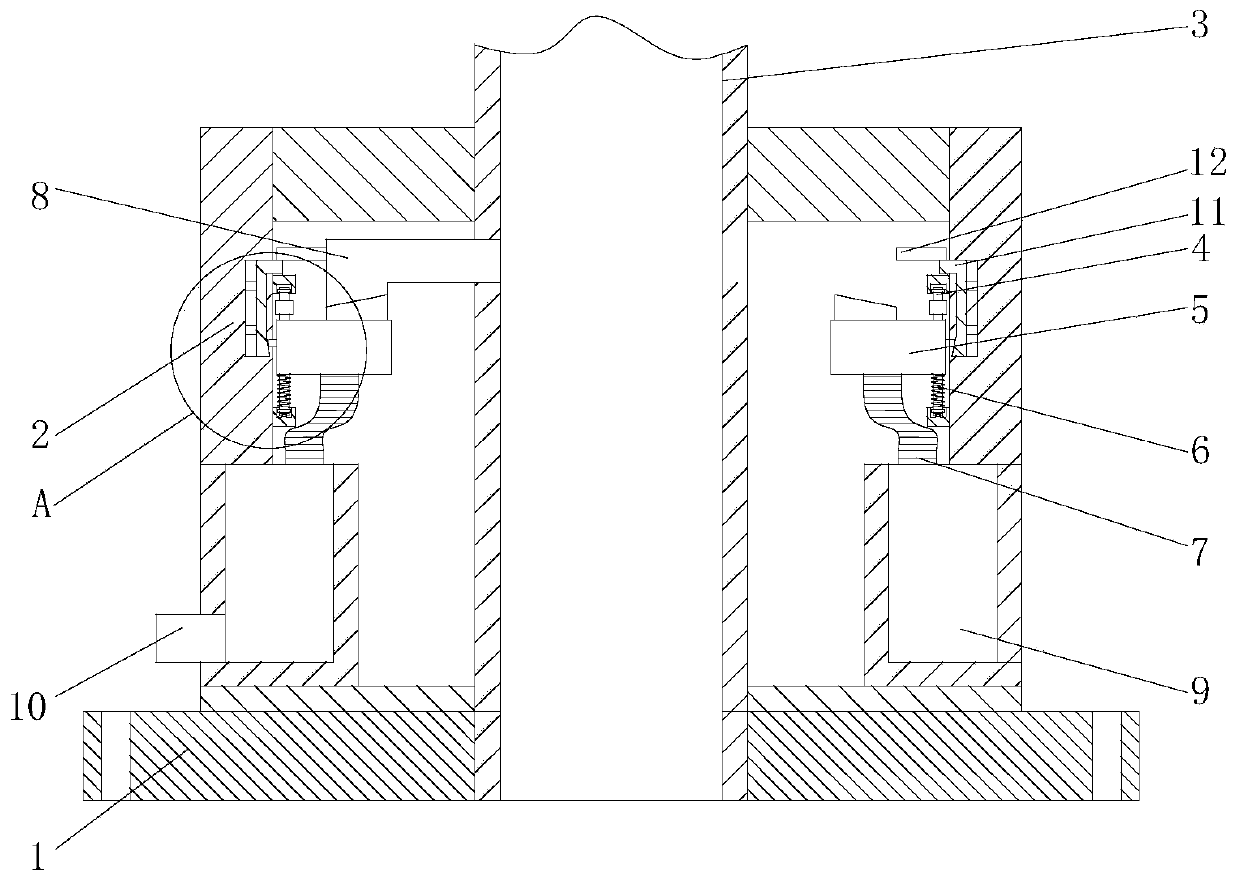
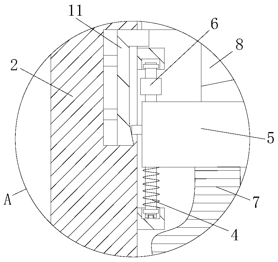
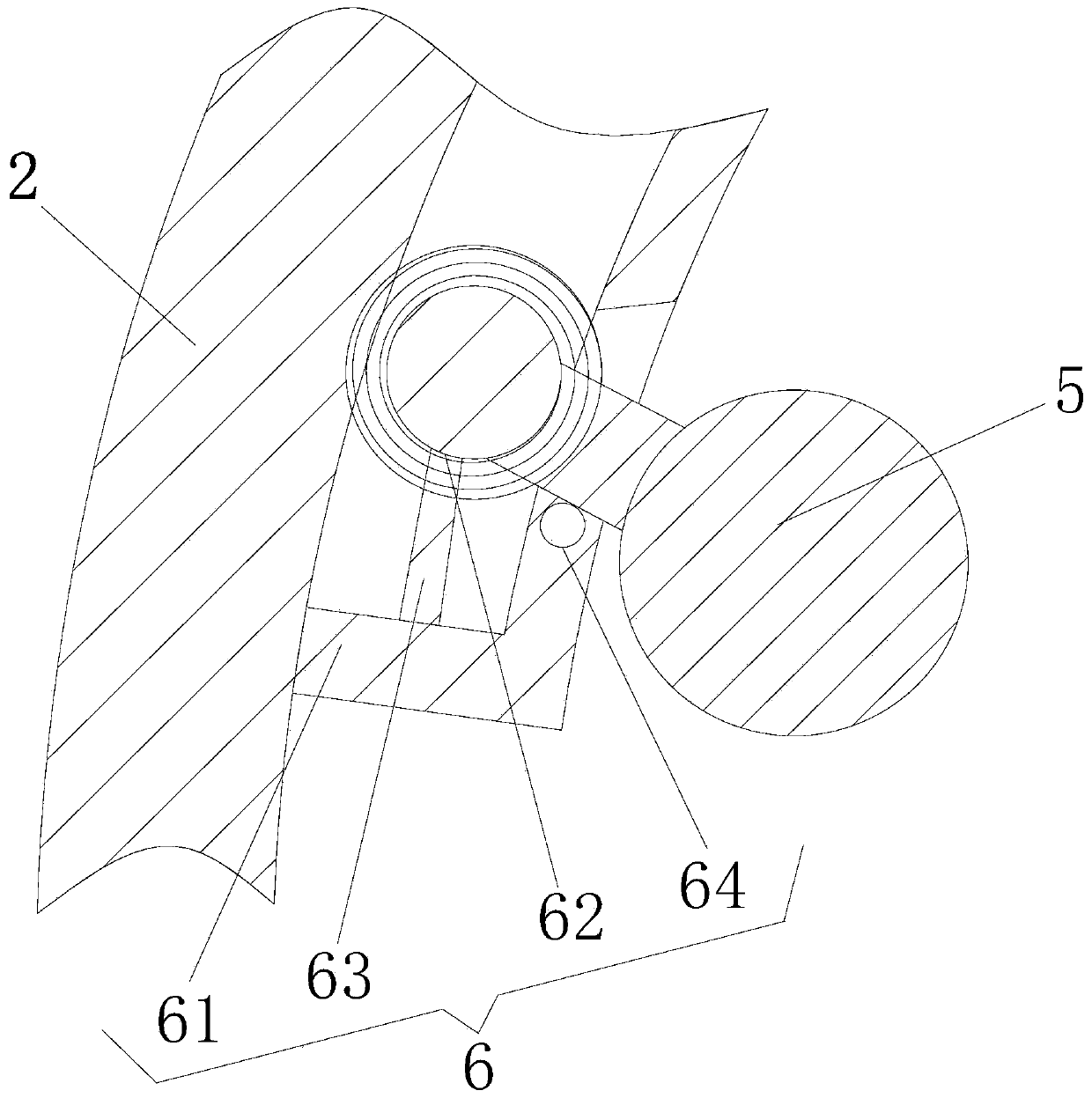
[0024] see Figure 1-7 , a fluid slip ring for a single point mooring device, comprising a mounting flange 1, an outer ring 2 and an inner ring 3, the upper end of the mounting flange 1 is fixedly connected with the inner ring 3, and the outer wall of the mounting flange 1 is sleeved with Outer ring 2, a thrust bearing is fixedly installed between the mounting flange 1 and the outer ring 2, a rolling bearing is installed between the outer ring 2 and the inner ...


PUM


Abstract

The invention relates to the technical field of marine engineering, and discloses a fluid slip ring for a single-point mooring device. The fluid slip ring for the single-point mooring device comprisesa mounting flange, an outer ring and an inner ring, the inner ring is fixedly connected to the upper end of the mounting flange, and the outer ring is connected with the outer side wall of the mounting flange in a sleeving mode. Due to the regularity of the wind and wave in the ocean, the situation that an engineering ship rotates around the mooring device at a large angle in daily life is rare.The fluid slip ring is adopted in the single-point mooring device to sacrifice the ability to rotate at a large angle, and fluid communication is achieved through connection of an upper connecting head and a lowering connecting head, the rotation between the outer ring and the inner ring, the action of the sea wave and the force of the ship are fully borne by the outer ring and the inner ring, theacting force between the lower connecting head and the upper connecting head is constant, the wear is uniform and small, secondly, the requirement on the coaxiality is small, and mounting is more convenient. A high temperature and high pressure medium circulates in the lower connecting head and the upper connecting head. The fluid pressure has less influence on a sealing piece, and the fluid slipring is more widely used in the aspect of the temperature and pressure.

Description

technical field [0001] The invention relates to the technical field of marine engineering, in particular to a fluid slip ring for a single point mooring device. Background technique [0002] Single-point mooring means that the marine engineering ship is moored on another fixed or floating structure through a single point. The ship can rotate 360° around the structure with the wind and waves. Due to the wind vane effect, the moored ship It will be moored at the position with the least environmental force. For offshore oil and gas production, it must also have the function of fluid transfer. [0003] see figure 1 , the communication cavity between the inner and outer rings is sealed by a seal, and the wear and tear of the surface will cause the slip ring to leak, which restricts the service life of the fluid slip ring, and due to the large mass of the offshore engineering ship, the pressure on the slip ring is usually biased to one side , will lead to uneven wear of the seal...

Claims


Application Information

Patent Timeline
Patent Type & Authority Applications(China)
IPC IPC(8): F16L39/00F16L39/02F16L39/06B63B21/50
CPCB63B21/50F16L39/005F16L39/02F16L39/06
Inventor 陈刚
Owner 山东沂南园区开发建设有限公司
Features
  • R&D
  • Intellectual Property
  • Life Sciences
  • Materials
  • Tech Scout
  • Unparalleled Data Quality
  • Higher Quality Content
  • 60% Fewer Hallucinations
Learn More