
Wafer detection method

A detection method and wafer technology, applied in measurement devices, semiconductor/solid-state device testing/measurement, instruments, etc., can solve problems such as the inability to scan effective chips, the inability to calculate the wafer map by the SEM machine, and the large exposure unit. , to avoid a large number of chips not being scanned and inaccurate defect scanning, narrowing the range of scanning units, and improving scanning accuracy

Inactive Publication Date: 2020-06-05
SEMICON MFG ELECTRONICS (SHAOXING) CORP
View PDF0 Cites 2 Cited by
  • Summary
  • Abstract
  • Description
  • Claims
  • Application Information

AI Technical Summary

Problems solved by technology

[0004] Scanning in units of chips, the number of virtual chips (tens of thousands) is too large, which makes it impossible for the SEM machine to calculate the corresponding wafer map
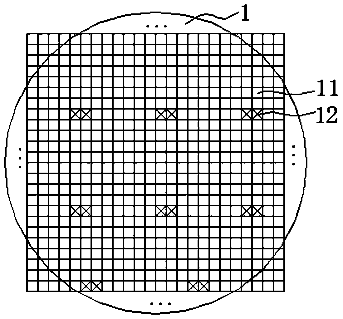
[0005] Scanning in units of exposure units reduces the number of virtual chips and enables the SEM machine to be able to calculate the corresponding wafer map, but there are some problems: the exposure unit is large, resulting in the edge of the wafer exceeding the wafer outline. A large number of effective chips in the exposure unit (not a complete exposure unit) cannot be scanned; and inaccurate defect scanning will miss many fatal defects

Method used


Image

  • Wafer detection method
  • Wafer detection method
  • Wafer detection method

Examples


Embodiment Construction

[0032] An embodiment of the present invention provides a wafer inspection method. The present invention will be described in further detail below in conjunction with the accompanying drawings and specific embodiments. The advantages and features of the present invention will become clearer from the following description. It should be noted that the drawings are all in a very simplified form and use imprecise scales, and are only used to facilitate and clearly assist the purpose of illustrating the embodiments of the present invention.

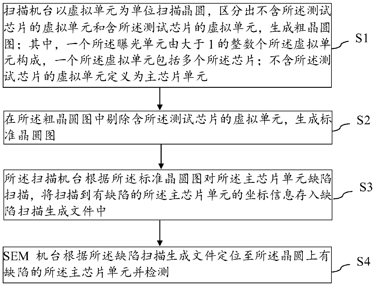
[0033] An embodiment of the present invention provides a wafer inspection method. The chips on the wafer include a main chip and a test chip, and the wafer is formed by repeated exposure by an exposure unit, such as figure 1 shown, including:

[0034] The scanning machine scans the wafer with a virtual unit as a unit, distinguishes a virtual unit not containing the test chip and a virtual unit containing the test chip, and generates a rough w...


PUM


Abstract

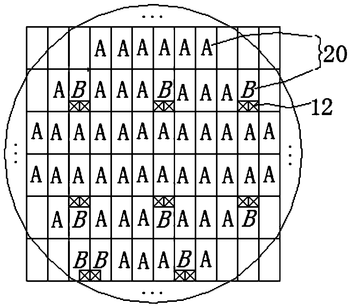
The invention provides a wafer detection method, which comprises the following steps: a scanning machine scanning a wafer by taking a virtual unit as a unit to generate a coarse wafer graph; wherein one exposure unit is composed of an integer number of virtual units greater than 1, and one virtual unit comprises a plurality of chips; removing a virtual unit containing a test chip from the coarse wafer graph to generate a standard wafer graph; the scanning machine scanning the defects of the main chip units according to the standard wafer diagram, and the SEM machine searching the defective main chip units on the wafer according to the defect scanning generation file and detects the defective main chip units. Compared with the mode that chips are scanned one by one by taking a single chip as a unit, the number of scanned virtual chips is reduced, so that an SEM machine table has the capability of calculating a corresponding wafer graph to carry out point-to-point automatic detection. Compared with the mode of scanning the wafer by taking the exposure unit as the unit, the contour size of the scanning unit is reduced by taking the virtual unit as the unit, and the edge of the wafer can be covered by more virtual units, so that a scanning machine can scan the wafer. As the scanning unit range is reduced, the scanning precision is improved.

Description

technical field [0001] The invention belongs to the technical field of integrated circuit manufacturing, and in particular relates to a wafer detection method. Background technique [0002] With the development of semiconductor technology, combined with the demand for chip cost reduction, the size of a single chip is getting smaller and smaller, and the number of chips contained on a corresponding wafer is increasing. There are tens of thousands of chips (die) on a wafer. The wafer includes the main chip and the test chip. The test chip is used for the process monitoring test of the wafer production process or the test after the production is completed. The wafer defect scanning test mainly depends on whether there is a defect on the main chip, but the test chip is different from the main chip. Therefore, during the wafer defect scanning test, the test chip will be mistaken for a defective abnormal chip, which will affect the judgment result of the wafer defect scanning tes...

Claims


Application Information

Patent Timeline
Patent Type & Authority Applications(China)
IPC IPC(8): G01N23/2251H01L21/66
CPCG01N23/2251H01L22/12H01L22/20
Inventor 熊俊剑
Owner SEMICON MFG ELECTRONICS (SHAOXING) CORP
Learn More