
Power equipment fault diagnosis method based on infrared image

An infrared image and power equipment technology, applied in the field of power equipment status monitoring and fault diagnosis, can solve problems such as relatively large impact, inspection time and planning arrangements cannot achieve the expected results, and failure to find faults in time to achieve intelligentization The effect of online monitoring

Active Publication Date: 2020-06-05
XI AN JIAOTONG UNIV
View PDF8 Cites 11 Cited by
  • Summary
  • Abstract
  • Description
  • Claims
  • Application Information

AI Technical Summary

Problems solved by technology

However, the disadvantages of this technology are also obvious, that is, during the inspection process, whether it is the discovery of suspicious points or the diagnosis of subsequent faults, it is greatly affected by human factors
After using a thermal imager to generate a large number of continuous detection pictures through long-distance and large-area scanning in a short period of time, it is often impossible to find faults in time when screening pictures only relying on manpower, and the inspection time and planning arrangements cannot achieve the expected results

Method used


Image

  • Power equipment fault diagnosis method based on infrared image
  • Power equipment fault diagnosis method based on infrared image
  • Power equipment fault diagnosis method based on infrared image

Examples


Embodiment Construction

[0032] The following will refer to the attached Figure 1 to Figure 4(c) Specific embodiments of the present disclosure are described in detail. Although specific embodiments of the present disclosure are shown in the drawings, it should be understood that the present disclosure can be embodied in various forms and should not be limited by the embodiments set forth herein. Rather, these embodiments are provided for more thorough understanding of the present disclosure, and to fully convey the scope of the present disclosure to those skilled in the art.

[0033] It should be noted that certain terms are used in the description and claims to refer to specific components. Those skilled in the art should understand that they may use different terms to refer to the same component. The specification and claims do not use differences in nouns as a way to distinguish components, but use differences in functions of components as a criterion for distinction. "Includes" or "comprises"...


PUM


Abstract

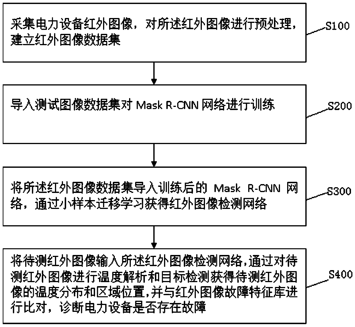
The invention discloses a power equipment fault diagnosis method based on an infrared image, and the method comprises the steps: collecting the infrared image of power equipment, carrying out the preprocessing of the infrared image, and building an infrared image data set; importing the test image data set to train the Mask R-CNN network; importing the infrared image data set into a trained Mask R-CNN network, and obtaining an infrared image detection network through small sample transfer learning; inputting a to-be-detected infrared image into the infrared image detection network, performingtemperature analysis and target detection on the to-be-detected infrared image to obtain temperature distribution and a region position of the to-be-detected infrared image, and comparing the temperature distribution and the region position with the infrared image fault feature library to diagnose whether the power equipment has a fault or not. According to the invention, an infrared temperature measurement fault automatic diagnosis method combining a pixel-level target detection technology and a temperature analysis method is introduced, and automatic diagnosis of power equipment faults can be realized.

Description

technical field [0001] The disclosure belongs to the field of state monitoring and fault diagnosis of electric equipment, and in particular relates to an infrared image-based fault diagnosis method for electric equipment. Background technique [0002] Infrared temperature measurement technology uses infrared thermal imaging cameras to detect infrared radiation emitted by objects, and converts the invisible radiation images through a series of conversion processes to obtain an intuitive temperature distribution map of the equipment, so as to realize the detection of abnormal temperature points or abnormal temperature distribution of substation equipment probing. In recent years, infrared temperature measurement and diagnosis technology has been very mature and widely used in various industries. When using this technology for substation inspection, it is generally necessary to quickly scan a large area of ​​the equipment under test to monitor the overall heating status of the...

Claims


Application Information

Patent Timeline
Patent Type & Authority Applications(China)
IPC IPC(8): G06K9/32G06N3/04G06Q50/06G01J5/00
CPCG06Q50/06G01J5/00G01J5/0003G01J2005/0077G06V10/25G06N3/045
Inventor 董明王彬郭晨希夏昌杰任明宋波张崇兴谢佳成胡一卓
Owner XI AN JIAOTONG UNIV
Learn More