
An insulated terminal and its high-voltage switch

A technology of insulating terminals and insulating shells, which is applied in the direction of connection insulation, air switch parts, multi-conductor connectors, etc., can solve the problems of easy heat accumulation of conductive joints, easy loosening of connecting ends, and drying of connecting ends, so as to avoid Accumulated heat damages components, promotes continuous effectiveness, and facilitates waterproof use

Active Publication Date: 2021-04-20
广东通贝电力实业有限公司
View PDF5 Cites 0 Cited by
  • Summary
  • Abstract
  • Description
  • Claims
  • Application Information

AI Technical Summary

Problems solved by technology

[0004] However, there are still relatively obvious defects in its use: 1. The size of the wiring screw hole in the above-mentioned device is single, which can only be adapted to a kind of conductive joint, and in the actual use process, the thickness of the conductive joint of different equipment The specifications are diverse, so the applicable environment of the above-mentioned device is relatively limited. In a complex environment, it is necessary to be equipped with a variety of insulated terminals, which is time-consuming and labor-intensive to install; 3. The above-mentioned device sets the drying bag on the side of the drainage plate close to the insulating sleeve, so these drying bags can only absorb and dry the moisture at both ends of the insulating terminal, but cannot dry the connecting end of the conductive joint. Dry, with limited drying effect and lack of pertinence; 4. The above-mentioned device lacks the necessary heat dissipation structure, which makes it easy to accumulate heat at the conductive joint, thus affecting the service life of the device

Method used


Image

  • An insulated terminal and its high-voltage switch
  • An insulated terminal and its high-voltage switch

Examples


Embodiment Construction

[0022] The following will clearly and completely describe the technical solutions in the embodiments of the present invention with reference to the accompanying drawings in the embodiments of the present invention. Obviously, the described embodiments are only some, not all, embodiments of the present invention. Based on the embodiments of the present invention, all other embodiments obtained by persons of ordinary skill in the art without making creative efforts belong to the protection scope of the present invention.

[0023] see Figure 1-2 , the present invention provides a technical solution:

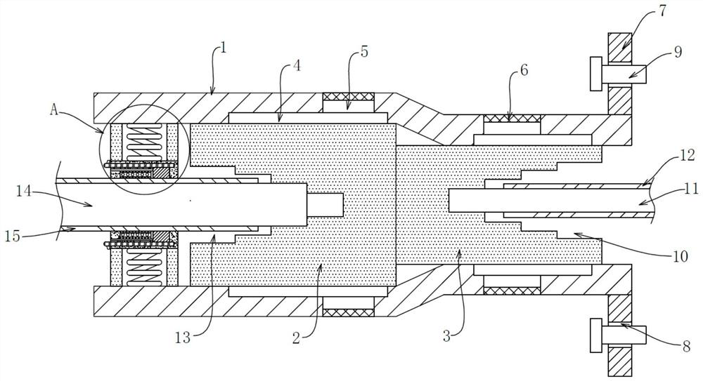
[0024] An insulated terminal includes an insulating housing 1. A first conductive block 2 and a second conductive block 3 are fixedly arranged inside the insulating housing 1. The first conductive block 2 and the second conductive block 3 are connected and can conduct electricity.

[0025] One end of the second conductive block 3 away from the first conductive block 2 is provided ...


PUM


Abstract

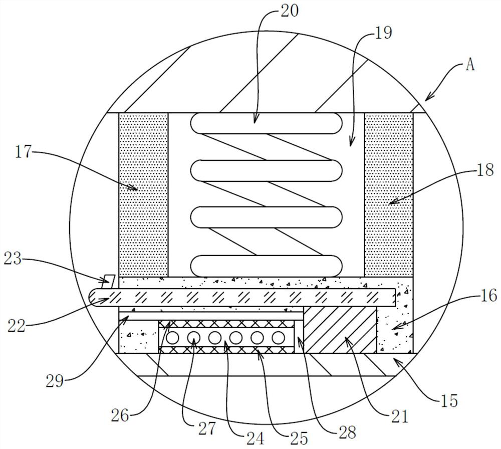
The invention discloses an insulated terminal and a high-voltage switch thereof, comprising an insulated casing, a first trapezoidal connection hole is opened at the end of the first conductive block away from the second conductive block, and a trapezoidal connection hole is inserted in the first trapezoidal connection hole. The first conductive rod, the elastic snap ring is fitted with a heat conduction element at a position close to the first insulating heat conduction adhesive layer, the heat conduction element is connected to the heat dissipation element, an installation groove is opened in the elastic snap ring, and the installation A plurality of drying beads are arranged in the groove, and a heat transfer element is fixedly arranged on a side of the installation groove close to the heat conduction element, and the heat transfer element and the heat conduction element are fixedly connected. The invention provides an insulating terminal, which can adapt to conductive rod connectors of various thicknesses and specifications for different equipment, has a built-in elastic snap ring to ensure stable connection, and has the function of waterproof and heat dissipation, and the dry beads can be repeatedly heated by the heat conduction of the heat transfer member. Drying and repeated use, the present invention also provides a high-voltage switch comprising the above-mentioned insulated terminal, which is convenient to use and is worthy of popularization.

Description

technical field [0001] The invention relates to the technical field of conductive devices, in particular to an insulating terminal and a high-voltage switch thereof. Background technique [0002] An insulated terminal is actually a piece of metal sealed in insulating plastic. There are holes at both ends for inserting wires, and there are screws for fastening or loosening. For example, two wires sometimes need to be connected and sometimes need to be disconnected. They can be connected with terminals and can be disconnected at any time without having to solder them or twist them together, which is very convenient and quick. [0003] In the prior art, a waterproof insulated terminal with the application number "201822178829.7" includes a conductive rod, the conductive rod is fixedly connected with an insulating sleeve, the insulating sleeve covers the conductive rod, and the two ends of the insulating sleeve are provided with wiring screw holes. The internal thread is connec...

Claims


Application Information

Patent Timeline
Patent Type & Authority Patents(China)
IPC IPC(8): H01R11/05H01R4/48H01R4/70H01H31/02
CPCH01H31/02H01R4/48H01R4/70H01R11/05
Inventor 沈文齐沈梦然
Owner 广东通贝电力实业有限公司
Learn More