Direct-buried type high-voltage cable automatic laying device and laying method

A high-voltage cable, automatic laying technology, applied in cable laying equipment and other directions, can solve the problems of large labor and high labor intensity.

Active Publication Date: 2020-06-05
南京飞阳输变电工程有限公司
View PDF11 Cites 16 Cited by
  • Summary
  • Abstract
  • Description
  • Claims
  • Application Information

AI Technical Summary

Problems solved by technology

Because the cable itself is very load-bearing, the process of handling the cable requires a lot of labor, and the labor intensity is also relatively high.

Method used


Image

  • Direct-buried type high-voltage cable automatic laying device and laying method
  • Direct-buried type high-voltage cable automatic laying device and laying method
  • Direct-buried type high-voltage cable automatic laying device and laying method

Examples


Embodiment 1

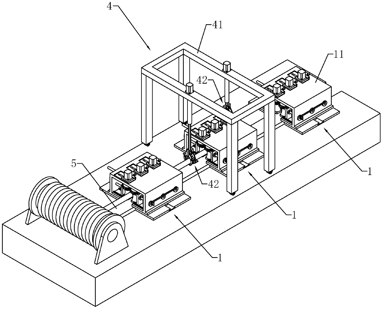
[0048] Example 1: Reference figure 1 , a direct buried high-voltage cable automatic laying device, including a traction device 4 and a conveying device 1, the conveying device 1 straddles the cable trench 5 and one conveying device 1 is set every 10 meters. The reel of the reeled cable is placed at one end of the cable trench 5, first the cable is fixed on the traction device 4, and then the traction device 4 is moved so that the cable passes through the conveying device 1, and each conveying device 1 plays a role in conveying the cable. The role of preventing cables from dragging on the ground. After a cable is transported to the designated position, the cable is unloaded from the conveying device 1 and the traction device 4, so that the cable falls in the cable trench 5. This method replaces the manual handling of the cable and reduces the amount of labor.

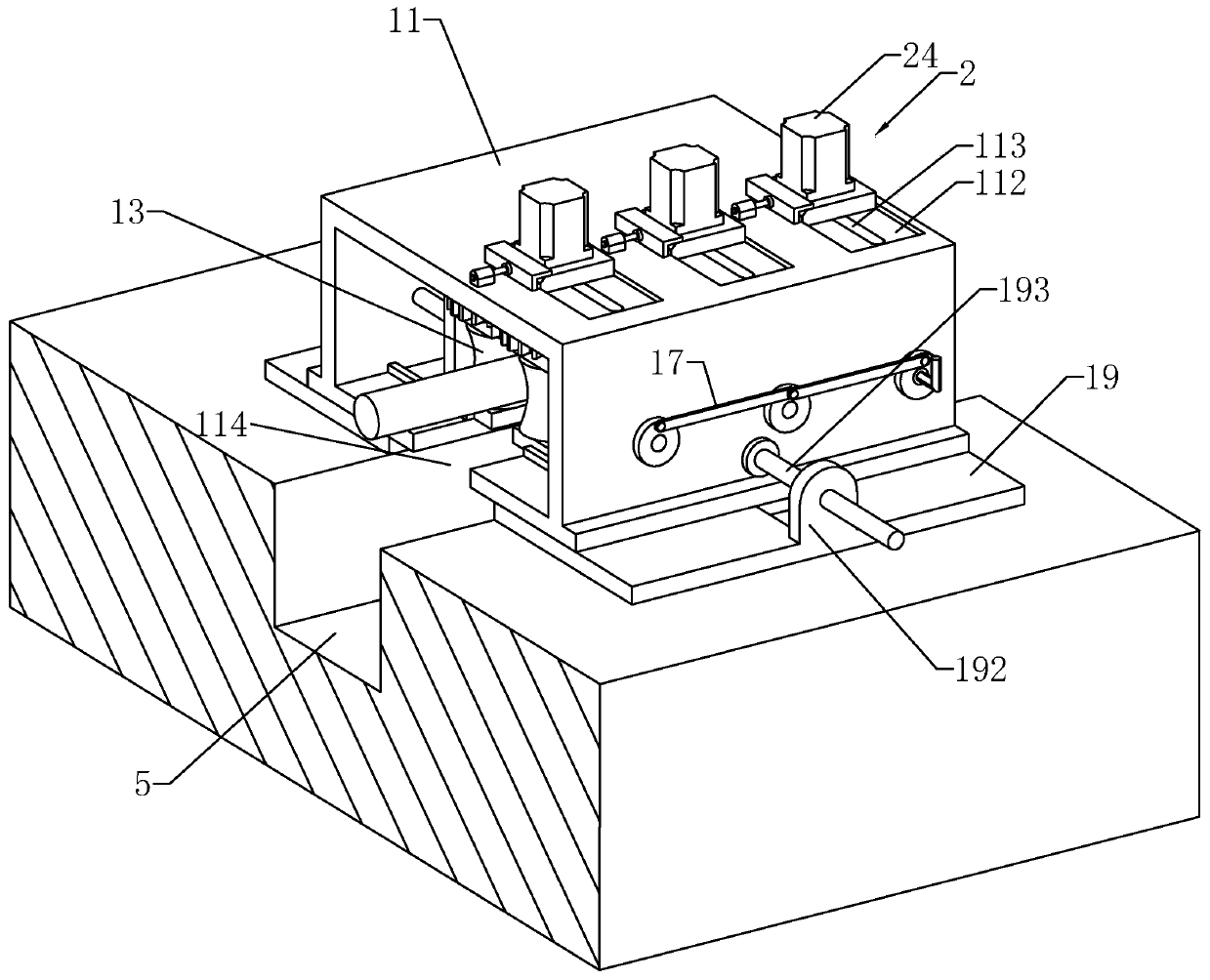
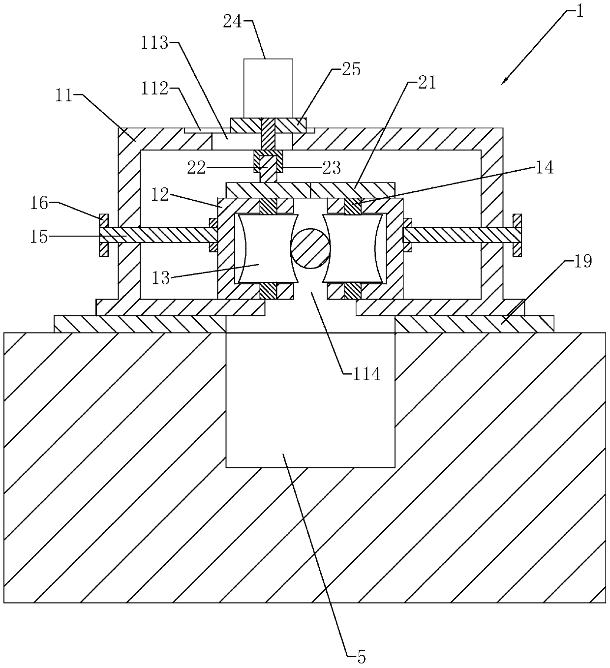
[0049] refer to figure 2 and image 3 , the conveying device 1 comprises a support frame 11 straddling the cable t...

Embodiment 2

[0061] Embodiment 2: Referring to the figure, a method for automatic laying of directly buried high-voltage cables includes the following steps:

[0062] 1. First, place the conveying device 1 on the cable trench 5 at equal intervals of 5-10 meters each;

[0063] 2. Fix one end of the cable on the traction device 4, and push the traction device 4 to move along the length direction of the cable trench 5;

[0064] 3. When the cable is close to the conveying device 1, the claws 42 close to the conveying device 1 open to send off the clamping of the cable, and at the same time the claws 42 move upwards driven by the servo motor 45;

[0065] 4. When the first claw 42 passes the conveying device 1 and the second claw 42 is close to the conveying device 1, the first claw 42 moves downward and gathers to clamp the cable, and then the second claw 42 Two jaws 42 open, send off the clamping of the cable and move upward;

[0066] 5. When the second claw 42 passes through the conveying d...


PUM


Abstract

The invention discloses a direct-buried type high-voltage cable automatic laying device. The direct-buried type high-voltage cable automatic laying device comprises a traction device for pulling a cable along the length direction of the cable trench, and a plurality of conveying devices arranged above the cable trench. The conveying device comprises a supporting frame and a plurality of sets of clamping wheels which are rotationally connected to the supporting frame and used for clamping cables. The clamping wheels are distributed in the length direction of the supporting frame. A plurality ofgroups of U-shaped sliding seats in one-to-one correspondence with the clamping wheels are arranged on the supporting frame in a mirroring manner, and the clamping wheel is located in the middle of the sliding base and is rotationally connected to the sliding base at the same time. Adjusting screw rods connected to the supporting frame in a threaded mode are horizontally and rotationally connected to the faces, deviating from each other, of the same set of sliding bases, a driving assembly used for driving the clamping wheels to rotate relatively is further arranged on the supporting frame, and an opening allowing a cable to be disengaged from the supporting frame downwards is formed in the supporting frame. The direct-buried type high-voltage cable automatic laying device has the advantages that the cable directly falls down to be rapidly separated from the conveying device, and then the effect of saving labor force is achieved.

Description

technical field [0001] The invention relates to the field of cable laying devices, more specifically, it relates to a direct-buried high-voltage automatic cable laying device and a laying method. Background technique [0002] As the advantage of laying cables underground is stronger than that of laying cables on the ground, most of them use underground wiring. Common forms of underground cable laying include cable tunnels, cable ducts, and direct-buried cable trenches. The direct-buried cable laying is a method of digging cable trenches on the ground, placing the cables in the cable trenches, and then backfilling with sand. Cable laying method. [0003] The Chinese patent with the publication number CN206720454U discloses a cable conveyor, which includes a base, a guide frame installed at both ends of the base, and two annular crawlers arranged on the base along the length direction of the base. The upper guide roller and the lower guide roller are rotated along the width ...

Claims


Application Information

Patent Timeline
IPC IPC(8): H02G1/06
CPCH02G1/06
Inventor 周露
Owner 南京飞阳输变电工程有限公司
Why Eureka
Try Eureka