
Power failure detection method of communication equipment

A technology for power-down detection and communication equipment, which is applied to electrical components, data processing power supplies, and distribution line transmission systems, etc. Waste of system resources, avoid unnecessary losses, and ensure the effect of resource utilization

Active Publication Date: 2020-06-05
磐基技术有限公司
View PDF13 Cites 0 Cited by
  • Summary
  • Abstract
  • Description
  • Claims
  • Application Information

AI Technical Summary

Problems solved by technology

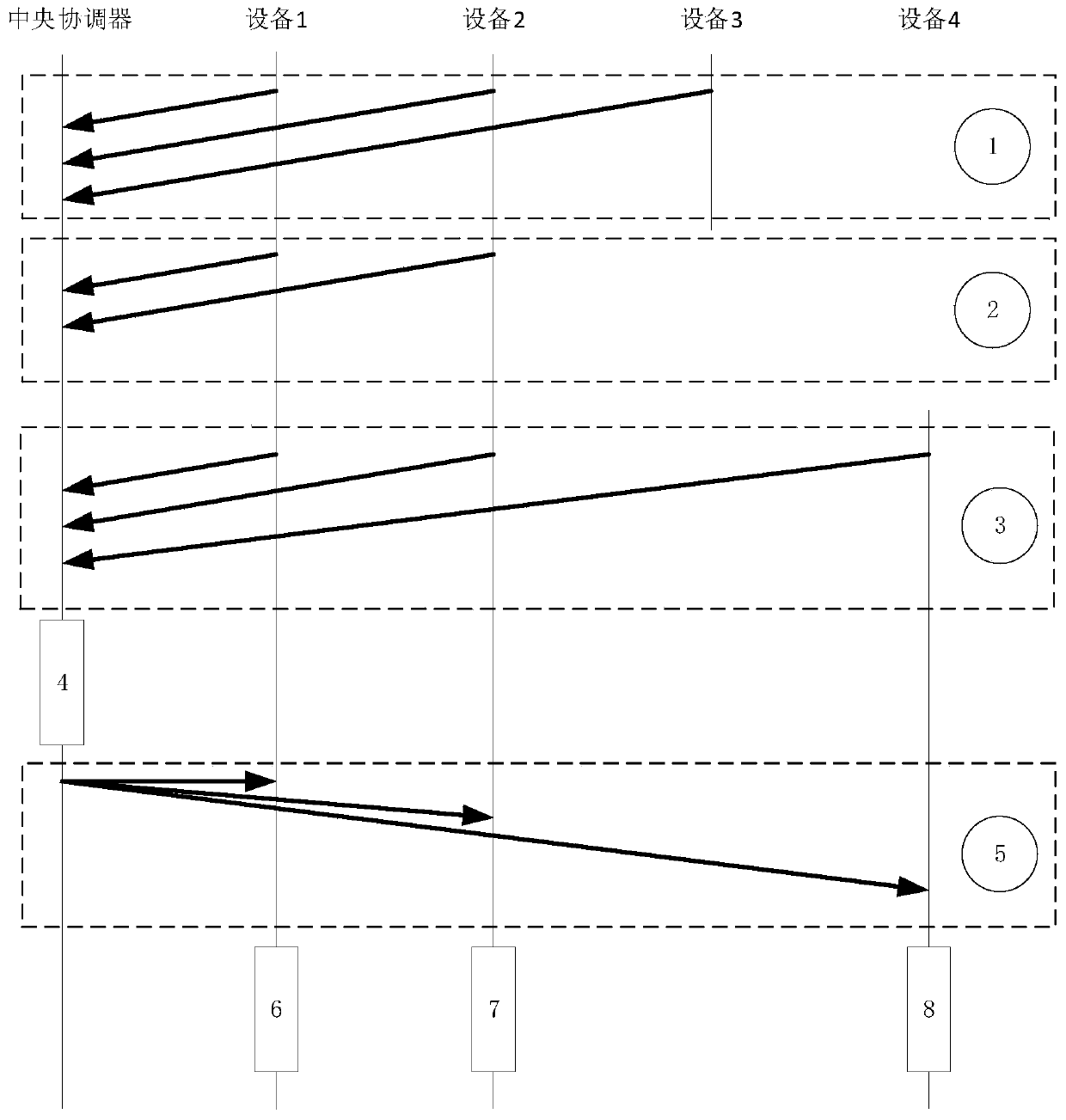
[0005] Disadvantage of prior art 1: Since the central coordinator cannot timely obtain the current information of the leaving device in the passive release state, if the device is repeatedly powered on and off within a detection cycle, the central coordinator cannot judge whether the device is new or not. access device
[0007] The disadvantage of this solution is: when setting the timeout mechanism, since the time is not fixed, if the setting time is too long, the device in the prior art has been powered on and off but the central coordinator has not monitored the status update of the device, so that the device It is impossible to reconnect to the network. If the setting time is too short, it will affect the efficiency of data transmission in the network. Since all devices in the network send data based on the competition mechanism, once the timeout time is too short, it will frequently occupy the network. resources, resulting in a waste of network resources
[0008] Usually, we will choose a compromise solution to monitor at a specific point in time, but this solution cannot avoid timely updating of the status of the device in case of abnormal power failure

Method used


Image

  • Power failure detection method of communication equipment
  • Power failure detection method of communication equipment

Examples


Embodiment

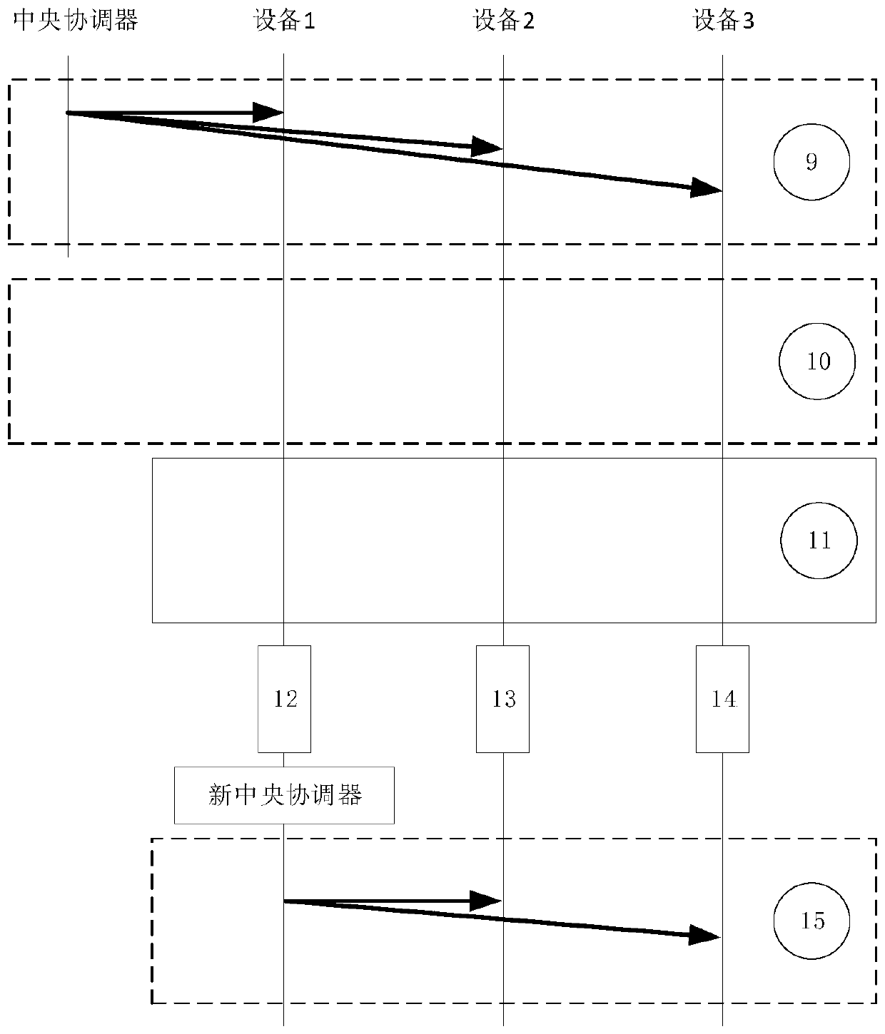
[0037] The central coordinator carries the MAC addresses of all devices in the current network and the corresponding network internal ID number mapping table in the public broadcast information. By updating the mapping table in the public broadcast information, all devices in the current network can judge accordingly The status of the equipment in the network, and then optimize the network connection status of the equipment to achieve the effect of full utilization of resources.

[0038] This scheme is applicable to all non-central network communications. There is no fixed central device in the entire network. All devices (nodes) in the network compete to recommend a pseudo-center (central coordinator) to manage the devices (nodes) in the current network. If the current pseudo center (central coordinator) leaves the current network, other devices will re-elect a new pseudo center (central coordinator) to manage.

[0039] Step 1: All devices in the network send the current stat...


PUM


Abstract

A power failure detection method of communication equipment comprises the following steps: a central coordinator carries MAC addresses of all devices in a current network and a network internal ID number mapping table corresponding to the MAC addresses in public broadcast information, the mapping table in the public broadcast information is updated, all the devices in the current network judge thestates of the devices in the network according to the mapping table, and then the network connection state of the devices is optimized. The state information of each device in the current network needs to be updated in time in a communication system to prevent waste of system resources, caused by occupation of network resources due to unnecessary factors, so timeliness of equipment state updatingis effectively guaranteed, unnecessary loss caused by failure of normal connection during equipment reconnection is avoided, and meanwhile, the resource utilization rate in a system network is also guaranteed.

Description

technical field [0001] The invention belongs to the technical field of communication equipment, and particularly relates to a power-down detection method of communication equipment. Background technique [0002] The closest existing technology to this technology is power line carrier communication, which belongs to the self-organizing network architecture, and the disconnection state of the device from the network is divided into two ways: active disconnection and passive disconnection. Among them, the active release means that the device actively sends a disconnection message to exit the current network, and the passive release means that the device passively leaves the current network due to external reasons without being controlled. [0003] Active release is a request sent by the device to the central coordinator to leave the network. After receiving the request, the central coordinator replies that the device left successfully and resends a new network device mapping ta...

Claims


Application Information

Patent Timeline
Patent Type & Authority Applications(China)
IPC IPC(8): H04B3/54H04L29/08G06F1/28
CPCH04B3/544G06F1/28H04L67/54
Inventor 邢远航傅鑫陈宁周博
Owner 磐基技术有限公司
Learn More