A Grain Storage Warehouse Temperature Control System
A technology of temperature control system and storage warehouse, applied in botany equipment and methods, agricultural machinery and implements, gardening, etc., can solve problems such as unfavorable storage grain quality preservation, temperature rise of stored grain, etc., to avoid grain deterioration and reduce temperature difference Effect
- Summary
- Abstract
- Description
- Claims
- Application Information
AI Technical Summary
Problems solved by technology
Method used
Image
Examples
Embodiment 1
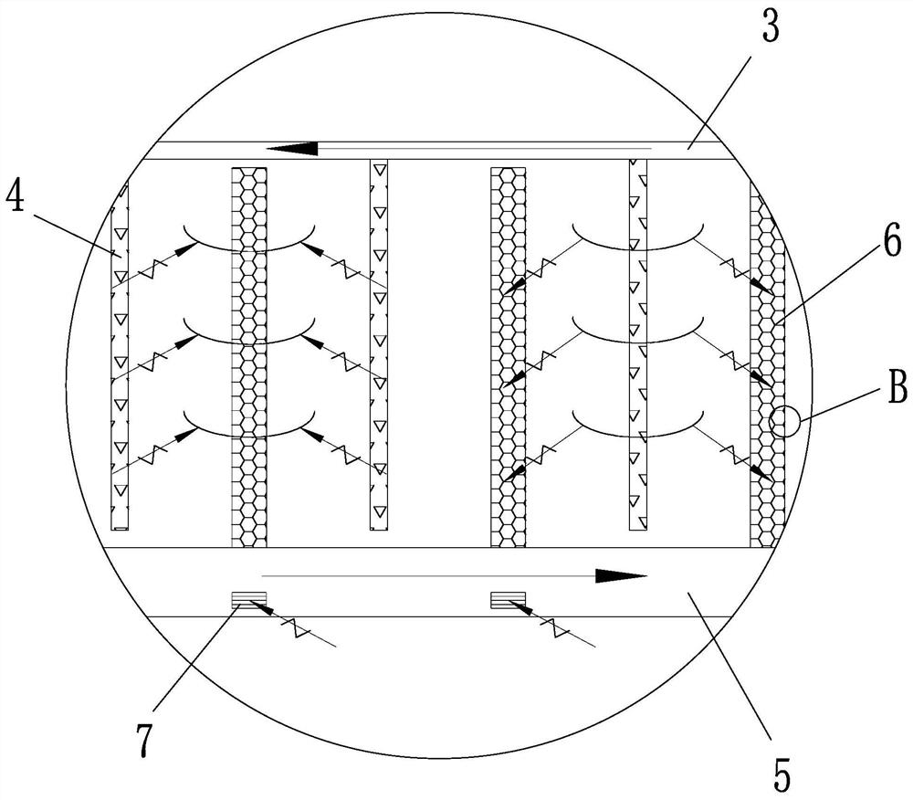
[0021] Embodiment 1: as figure 1 , 2As shown, a temperature control system for a grain storage bin includes a temperature control device 2 arranged on one side of the storage bin 1 along the wall. The temperature control device is connected with an air outlet pipe 4 and a return pipe 5, both of which are It is arranged horizontally around the inner wall of the storage bin. On the air outlet pipe, there are several longitudinally extending branch outlet pipes 4 arranged at intervals. On the return pipe, there are several longitudinally extending branch return pipes 6 arranged at intervals. The branch outlet pipe and the branch return pipe interval distribution. The air outlet pipe is located in the upper middle part of the storage bin and is lower than the inspection door, and the return pipe is located at the bottom of the storage bin. Return ports 7 are arranged at intervals on the return pipe. Air outlet pipes and return pipes are arranged on all inner walls separated fro...
Embodiment 2
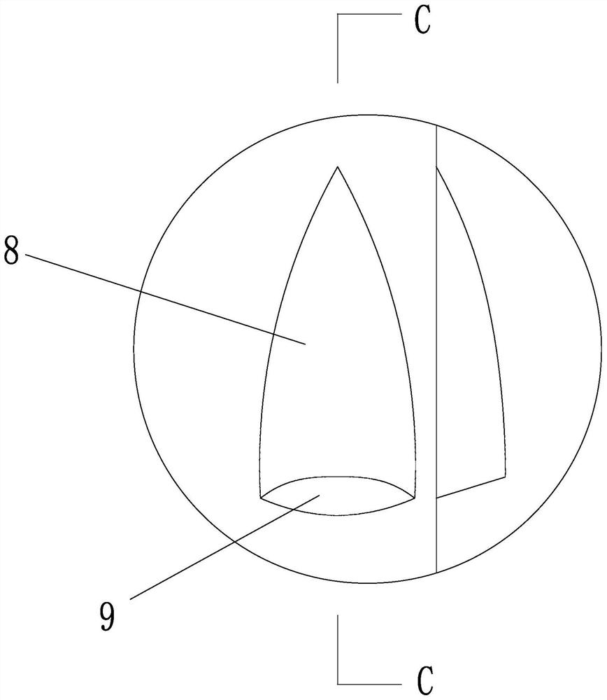
[0023] Embodiment 2: The structure of this embodiment is basically the same as that of Embodiment 1, the difference is that, as image 3 , 4 As shown, both the branch air duct and the branch return duct include an inner tube 10 and an outer tube 11 sleeved on the outside of the inner tube and bonded to the outer surface of the inner tube. The inner tube is densely covered with through holes 12 for air flow. The tube is densely covered with air guide holes integrally connected with the outer tube. The air guide holes include a cone part 8 and a hole part 9. The cone part is a conical surface structure protruding from the surface of the outer tube. Both sides of the cone part are integrated with the outer tube. Connected, the gap between the free end edge of the cone and the outer tube forms a hole, and the through hole on the inner tube corresponds to the cone.
[0024] Both the branch air pipe and the branch return pipe are composed of an inner pipe and an outer pipe. The inn...
Embodiment 3
[0025] Embodiment 3: The structure of this embodiment is basically the same as that of Embodiment 2, the difference is that, as Figure 5 As shown, the middle position of the cone is recessed along the direction of the generatrix of the cone and toward the direction of the inner tube, and the air guide groove 13 is in the shape of a cone surface, and the free end edge of the cone is in the shape of an "M". The middle position of the cone is extruded along the direction of the generatrix of the cone to form an air guide groove, so that the air guide groove has a conical surface. Due to the shape of the air guide groove, the free end edge of the cone part presents an "M" shape, and the air guide groove The plate that has been stamped into the cone can be squeezed by a roller with protrusions, and the protrusions on the roller can be used to form air guide grooves on the cone. The air guide groove divides the space inside the cone into left and right parts, and the air entering a...
PUM
 Abstract
Description
Claims
Application Information
 - R&D
- Intellectual Property
- Life Sciences
- Materials
- Tech Scout
- Unparalleled Data Quality
- Higher Quality Content
- 60% Fewer Hallucinations
Browse by: Latest US Patents, China's latest patents, Technical Efficacy Thesaurus, Application Domain, Technology Topic, Popular Technical Reports.
© 2025 PatSnap. All rights reserved.Legal|Privacy policy|Modern Slavery Act Transparency Statement|Sitemap|About US| Contact US: help@patsnap.com


