
TBC with fibrous reinforcement

a technology of fibrous reinforcement and tbc, which is applied in the direction of liquid fuel engines, vessel construction, marine propulsion, etc., can solve the problems of hotter combustion gas burning through the top of the piston, the piece starts to spall or chip, and the underlining airfoil base material is exposed, etc., to achieve the effect of greater strength

Active Publication Date: 2012-09-25
FLORIDA TURBINE TECH
View PDF1 Cites 28 Cited by
  • Summary
  • Abstract
  • Description
  • Claims
  • Application Information

AI Technical Summary

Benefits of technology

[0009]It is an object of the present invention to provide for a part covered with TBC to have greater strength when it comes to spoiling.
[0010]It is another object of the present invention to provide for a TBC with a fibrous reinforcement in order to strengthen the TBC and prevent spoiling.
[0012]It is another object of the present invention to provide for a TBC with a fibrous reinforcement in which the fibers are attached to a bond coat in order to limit the fbers from being pulled away from the substrate.
[0013]It is another object of the present invention to allow for higher combustion temperatures in a diesel engine.
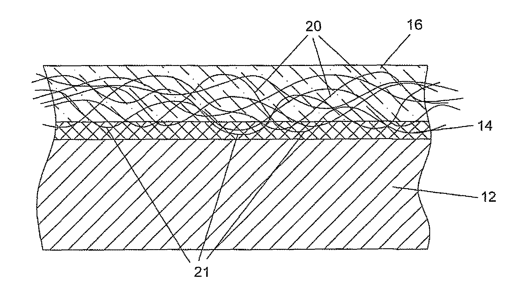
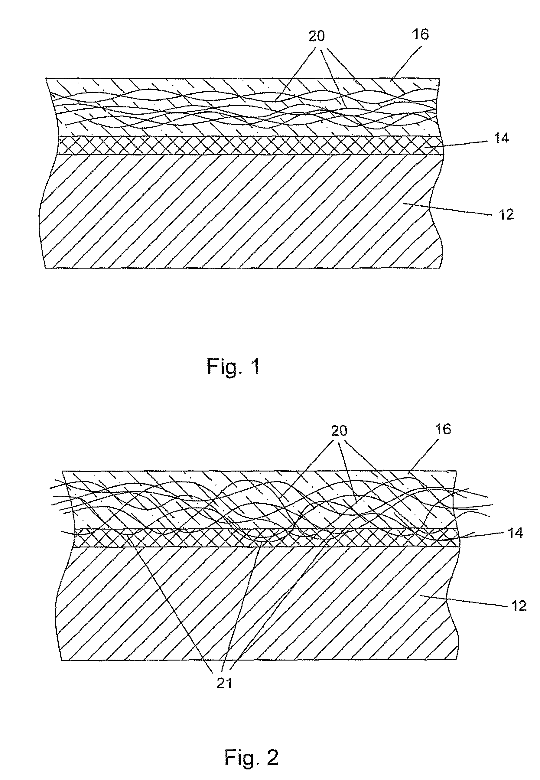
[0014]The present invention is directed to a part used in a gas turbine engine which requires a TBC in order to protect the part from the extreme high temperatures. The part can be a combustor liner or a transition duct or a turbine airfoil, or any part even used outside of a gas turbine engine that requires a TBC to protect the surface and the part from the extreme temperatures from the hot gas flow. The TBC layer on the part includes metal fibrous reinforcements embedded in the TBC layer to provide reinforcement such that the TBC layer can be thicker than a non-fibrous reinforced layer, and therefore allow for a higher temperature exposure for the part. The fibers are about 0.1 mm in diameter, and are made of carbon nanotubes or other materials such as from nickel, cobalt, or iron based super alloys. Carbon nanotubes can be formed from very small diameters and offer high temperature resistance as well as very good heat transfer capabilities.

Problems solved by technology

However, when the TBC layer gets too thick, pieces start to spall or chip off and eventually the underlining airfoil base material is exposed to the high gas stream temperature due to lack of TBC protection.
However, the hotter combustion gas tends to burn through the top of the piston.

Method used


Image

  • TBC with fibrous reinforcement
  • TBC with fibrous reinforcement

Examples


Embodiment Construction

[0017]The present invention provides for a method of reinforcing the TBC on the blade so that the TBC will not spall or chip off of the blade surface and therefore expose the blade surface to high temperatures above the safe operating range of the blade material. The present invention is also used for any part that requires a TBC layer for thermal protection, such as a combustor liner or the transition ducts in an industrial gas turbine engine. The fibers act to strengthen the TBC properties in tension and reduce the chance for a spalled piece to break off from the TBC layer. FIG. 1 shows the present invention, in which a blade substrate 12 includes a bond coat 14 applied onto the substrate and a TBC 16 applied over the bond coat 14. This is the standard method of using a TBC on a turbine blade or vane. The TBC is generally about 1 mm in thickness. The present invention includes a plurality of metallic fibers 20 intertwined over the surface of the bond coat 14. The metallic fibers 2...


PUM

PropertyMeasurementUnit
Diameteraaaaaaaaaa
Temperatureaaaaaaaaaa

Abstract

A substrate exposed to high temperatures, the substrate having a TBC layer that includes fibers of reinforcing material to add strength to the layer of TBC. The fibers are made from carbon nanotubes to withstand the high temperatures, and have a diameter of about 0.1 mm or less in order that a thin layer of TBC can completely cover and embed the fibers within the layer. A bond coat is applied to the substrate and the fibers are attached to the bond coat to limit the fibers from being pulled away from the substrate. The carbon nanotubes also provide for improved heat transfer through the TBC to improve the cooling capability of the TBC.

Description

CROSS-REFERENCE TO RELATED APPLICATIONS[0001]This application claims the benefit to an earlier filed Regular patent application Ser. No. 11 / 337,880 filed on Jan. 21, 2006 and entitled TURBINE AIRFOIL WITH FIBROUS REINFORCED TBC; which claims the benefit to an earlier filed Provisional Application Ser. No. 60 / 716,577 filed on Sep. 12, 2005 and entitled TURBINE AIRFOIL WITH FIBROUS REINFORCED TBC.FEDERAL RESEARCH STATEMENT[0002]None.BACKGROUND OF THE INVENTION[0003]1. Field of the Invention[0004]The present invention relates generally to a gas turbine engine, and in particular, to a TBC coating on a part exposed to a high temperature gas with a TBC applied.[0005]2. Description of the Related Art Including Information Disclosed Under 37 CFR 1.97 and 1.98[0006]In a gas turbine engine, the blade and vanes in the turbine section are exposed to the highest temperatures in the engine. Other parts of the engine are also exposed to high temperature gas flow such as the combustor liners. It is...

Claims


Application Information

Patent Timeline
IPC IPC(8): F01D5/14
CPCF01D5/282F01D5/288F05D2300/614F05D2300/702
Inventor RYZNIC, JOHN ESPANKS, JR., WILLIAM A.
Owner FLORIDA TURBINE TECH
Learn More