Multi-hole punching die

A porous stamping and mold technology, applied in the field of porous stamping molds, can solve problems such as different stamping position support

Active Publication Date: 2020-06-09
佛山好运电器配件有限公司
View PDF11 Cites 5 Cited by
  • Summary
  • Abstract
  • Description
  • Claims
  • Application Information

AI Technical Summary

Problems solved by technology

But this patent cannot support different stamping positions

Method used


Image

  • Multi-hole punching die
  • Multi-hole punching die
  • Multi-hole punching die

Examples


specific Embodiment approach 1

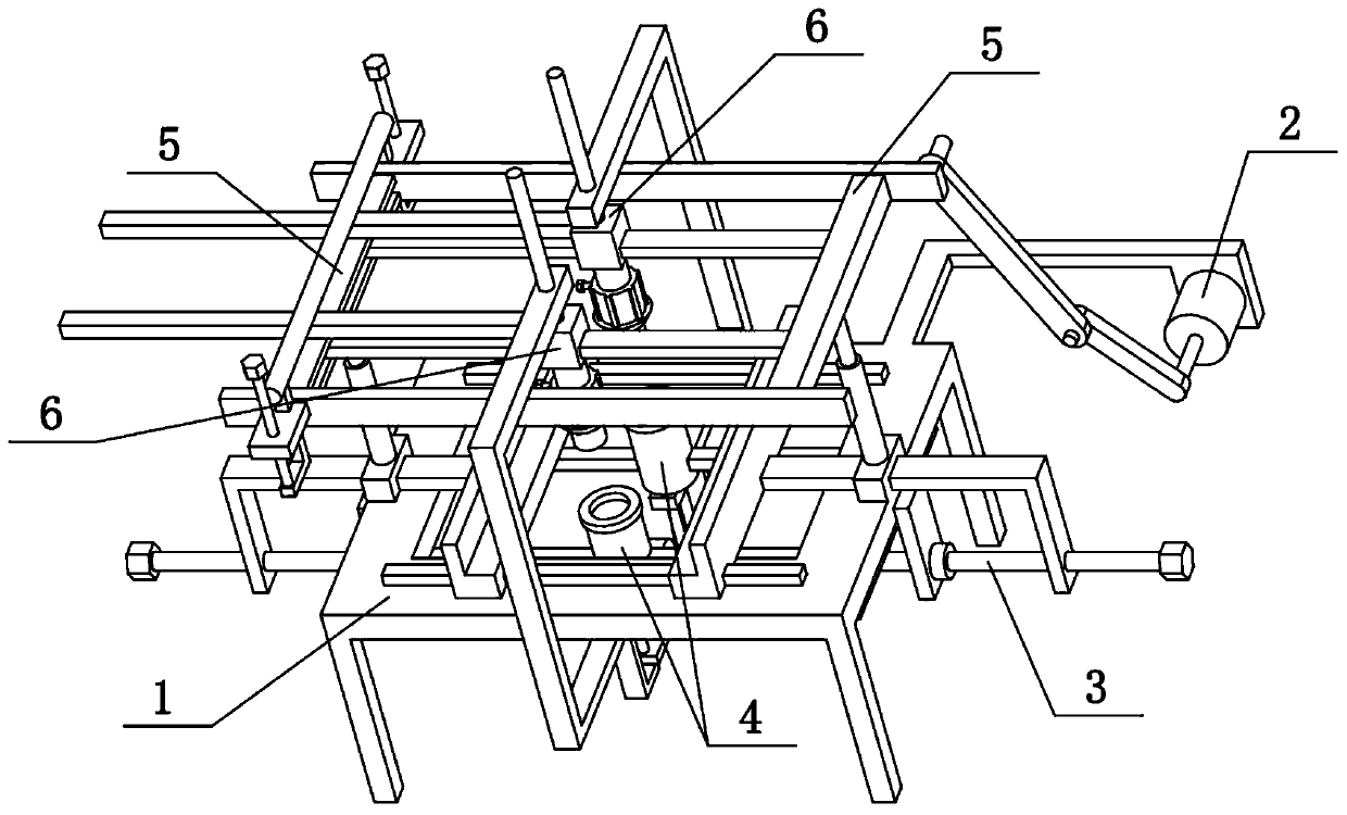
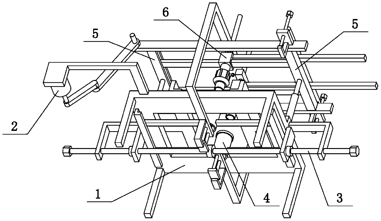
[0028] Combine below Figure 1-9 To illustrate the present embodiment, the present invention relates to a die, more specifically a porous stamping die, comprising a flat plate 1, support legs 103, rectangular holes 105, L-shaped bars 107, cylinder 4, transverse columns 401 and rubber rings 402. In the present invention, the two cylinders 4 can support the stamping position during stamping, and the positions of the two cylinders 4 can be adjusted to facilitate stamping at different positions.

[0029] The four corners of the lower side of the flat panel 1 are fixedly connected with supporting legs 103, the flat panel 1 is provided with a rectangular hole 105, and the left and right ends of the lower side of the flat panel 1 are fixedly connected with L-shaped bars 107, and the two L-shaped bars 107 are slidably connected with two transverse columns 401 in the front and rear directions, and the two cylinders 4 are respectively slidably connected on the two transverse columns 401...

specific Embodiment approach 2

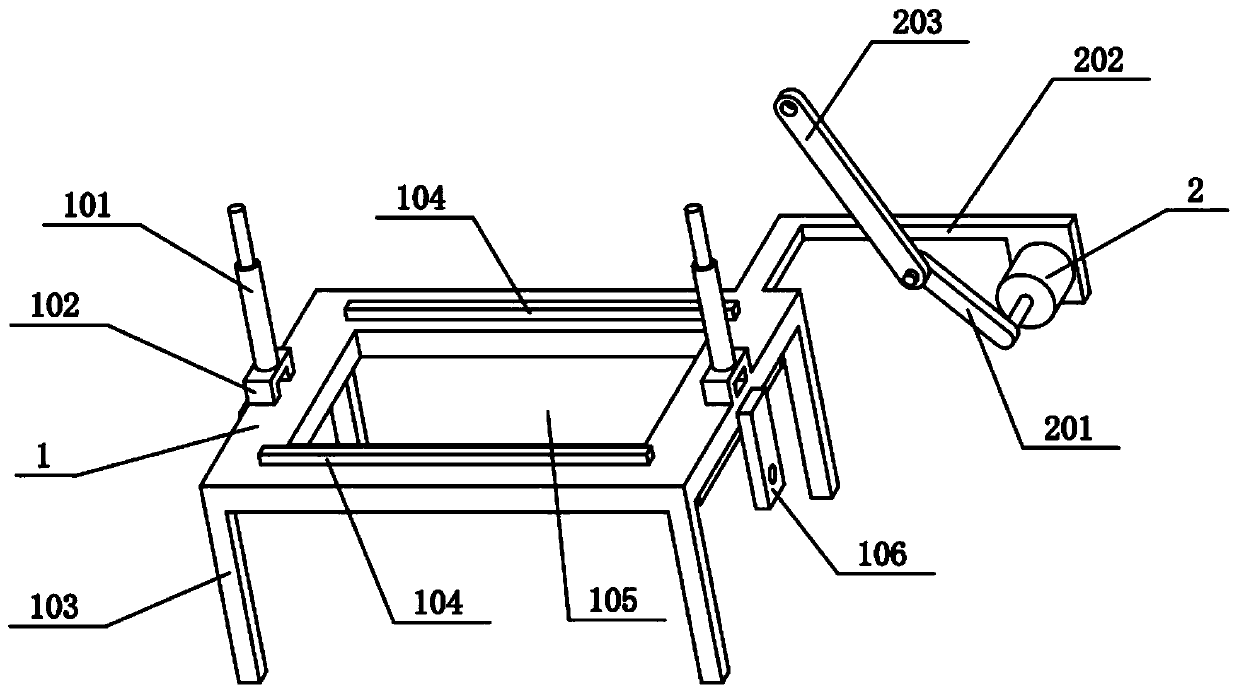
[0031] Combine below Figure 1-9To illustrate this embodiment, the porous stamping die also includes a fixed sleeve 102, a protruding piece 106, a bidirectional threaded screw 3, a limit ring 301, a threaded hole piece 302, a horizontal slide bar 303 and a clamp seat 305, and the left and right sides of the flat plate 1 Both are fixedly connected with lugs 106, the left and right ends of the upper side of the plate 1 are fixedly connected with fixed sleeves 102, and the two horizontal slide bars 303 are respectively slidably connected to the two fixed sleeves 102, and the outer ends of the two horizontal slide bars 303 Both ends are fixedly connected with threaded holes 302, and the left and right ends of the two-way threaded screw 3 are rotatably connected to the two lugs 106 respectively. Fit the outer sides of the two lugs 106 respectively, the helical directions of the left and right ends of the two-way threaded screw 3 are opposite, and the left and right ends of the two-...

specific Embodiment approach 3

[0033] Combine below Figure 1-9 To illustrate this embodiment, the porous stamping die also includes a cross rib 104 and a clamp rib 304, the outer sides of the two clamp seats 305 are fixedly connected with the clamp rib 304, the front and rear ends of the flat plate 1 are provided with the cross rib 104, two The holders 305 are slidably connected to the two transverse edges 104 in the left-right direction. When the two clamping seats 305 approach, the two clamping ribs 304 also approach, and then the metal plate to be stamped is clamped and fixed.


PUM


Abstract

The invention relates to a die, in particular to a multi-hole punching die. The multi-hole punching die comprises a flat plate, supporting legs, a rectangular hole, L-shaped strips, cylinders, transverse columns and rubber rings. When the multi-hole punching die performs punching, the two cylinders can bear a punching position, and the positions of the two cylinders can be adjusted to facilitate punching at different positions. The four corners of the lower side of the flat plate are fixedly connected with the supporting legs, the flat plate is provided with the rectangular hole, the left andright ends of the lower side of the flat plate are fixedly connected with the L-shaped strips, the two transverse columns are slidably connected between the two L-shaped strips in the front-right direction, the two cylinders are slidably connected to the two transverse columns in the left-right direction respectively and penetrate through the rectangular hole, and the upper sides of the two cylinders are provided with the rubber rings.

Description

technical field [0001] The invention relates to a mold, more specifically a porous stamping mold. Background technique [0002] The application number is CN201822141203.9, which discloses a double-process hollow tube porous stamping die. This utility model discloses a double-process hollow tube porous stamping die, including: an upper mold base, a lower mold base and a bracket. The first process A fixed mandrel extending forward is arranged in the mandrel fixing seat, a floating mandrel extending forward is arranged in the mandrel fixing seat of the second process, and the first process punch includes spaced first punches and The second punch, the second process punch includes a third punch and a fourth punch corresponding to the positions of the first punch and the second punch, and the fixed mandrel is provided with a punch corresponding to the first process punch. Corresponding to the groove, the bottom of the floating mandrel is provided with a fifth punch and a sixth p...

Claims


Application Information

Patent Timeline
Patent Type & Authority Applications(China)
IPC IPC(8): B21D28/34B21D28/26B21D28/04
CPCB21D28/04B21D28/26B21D28/34
Inventor 张思宇
Owner 佛山好运电器配件有限公司
Why Eureka
Try Eureka