
Counterweight device and railway engineering vehicle

A technology for counterweight devices and engineering vehicles, which is applied to locomotives and other directions, and can solve problems such as affecting the counterweight effect, poor safety, and offset of counterweight blocks, so as to avoid vehicle unbalanced loads and potential safety hazards, improve operating efficiency, and solve unbalanced loads. load problem effect

Pending Publication Date: 2020-06-09
CRRC SHENYANG CO LTD
View PDF7 Cites 1 Cited by
  • Summary
  • Abstract
  • Description
  • Claims
  • Application Information

AI Technical Summary

Problems solved by technology

[0004] However, the technology of using fixed counterweights to counterweight vehicles is only feasible in theory. Since the on-site rails are different in age and loading conditions are very different, fixed counterweights cannot solve the actual partial load well. Problem; by adding a temporary counterweight to the vehicle, a lifting tool is required to move the counterweight, and after the counterweight is completed, there is no safety locking device, and the counterweight will shift, affecting the counterweight effect and poor safety

Method used


Image

  • Counterweight device and railway engineering vehicle
  • Counterweight device and railway engineering vehicle
  • Counterweight device and railway engineering vehicle

Examples


Embodiment 1

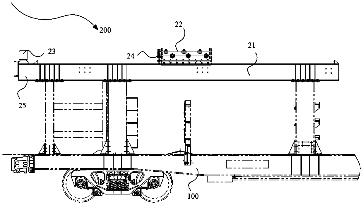
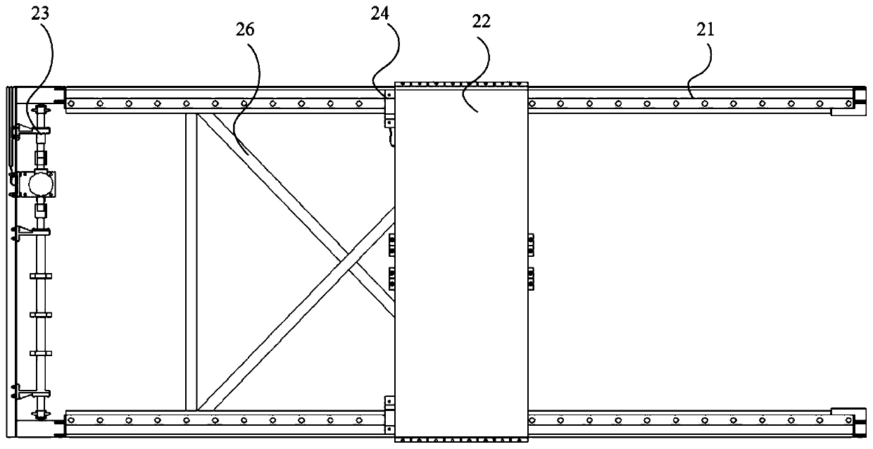
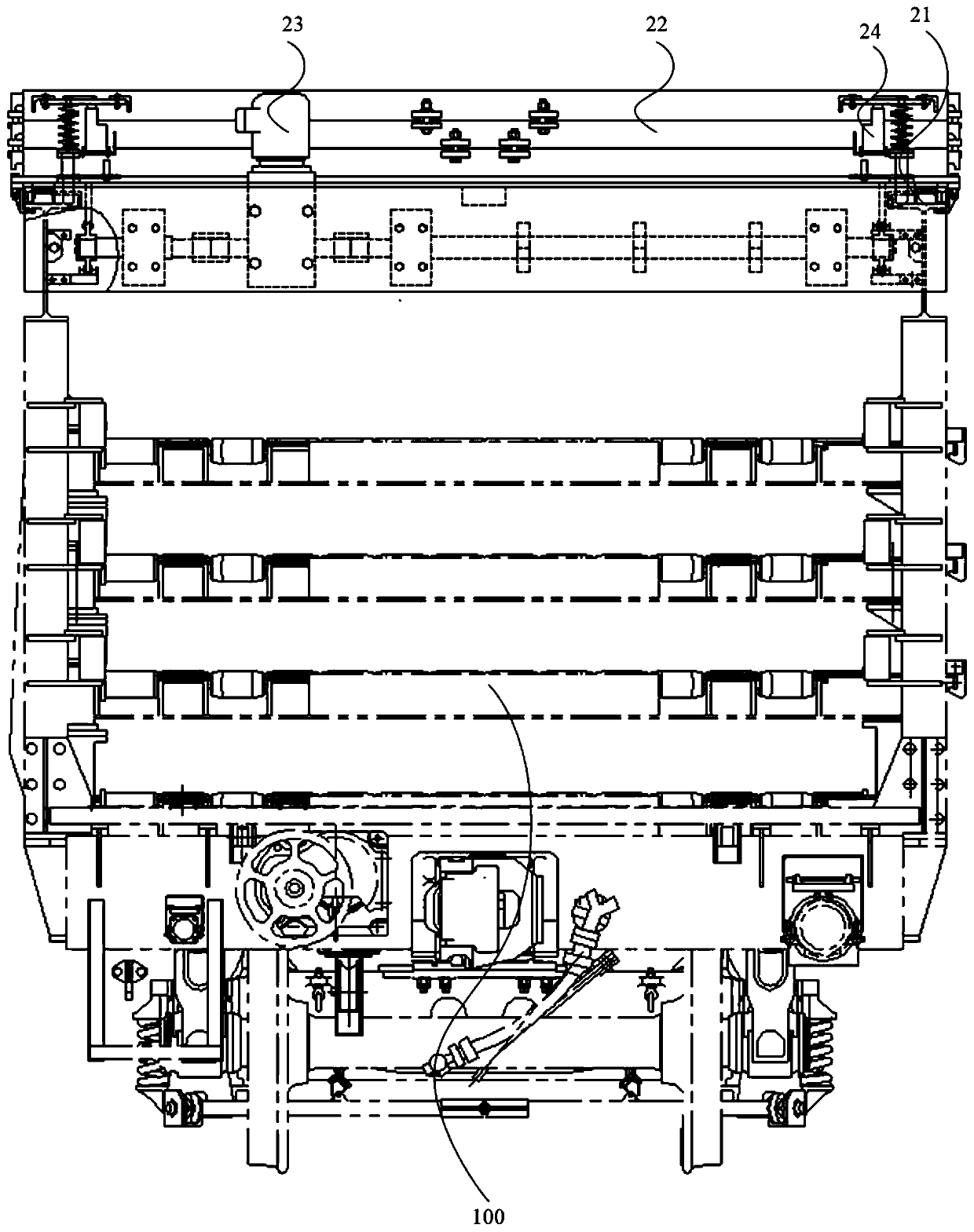
[0069] figure 1 The front view of the counterweight device provided by the embodiment of the present invention, figure 2 The top view of the counterweight device provided by the embodiment of the present invention, image 3 For the side view of the counterweight device provided by the embodiment of the present invention, refer to figure 1 , figure 2 and image 3 As shown, the present invention provides a counterweight device 200, comprising: track composition 21, counterweight composition 22, power system 23 and locking device 24; track composition 21 is installed on the railway engineering vehicle 100, counterweight composition 22 and power system 23 is installed on the track composition 21, the power system 23 is connected with the counterweight composition 22, and is used to drive the counterweight composition 22 to move on the track composition 21, and the locking device 24 is arranged on the counterweight composition 22, and is used to lock the counterweight composit...

Embodiment 2

[0089] The embodiment of the present invention also provides a railway engineering vehicle 100, including the counterweight device 200 described in the above embodiment.

[0090]Wherein, the counterweight device 200 includes: a track composition 21, a counterweight composition 22, a power system 23 and a locking device 24; the track composition 21 is installed on the railway engineering vehicle 100, and the counterweight composition 22 and the power system 23 are installed on the track composition 21 , the power system 23 is connected with the counterweight composition 22 for driving the counterweight composition 22 to move on the track composition 21 , and the locking device 24 is arranged on the counterweight composition 22 for locking the counterweight composition 22 on the track composition 21 .

[0091] In the railway engineering vehicle provided by the embodiment of the present invention, a counterweight device is arranged on the top of the vehicle body, wherein the count...


PUM


Abstract

The invention provides a counterweight device and a railway engineering vehicle. The counterweight device comprises a track assembly, a counterweight assembly, a power system and a locking device; thetrack assembly is installed on the railway engineering vehicle, the balance weight assembly and the power system are installed on the rail assembly, the power system is connected with the counterweight assembly and is used for driving the counterweight assembly to move on the rail assembly, and the locking device is arranged on the counterweight assembly and is used for locking the counterweightassembly on the rail assembly. The unbalance loading problem of the railway engineering vehicle can be effectively solved.

Description

technical field [0001] The invention relates to the technical field of rail trains, in particular to a counterweight device and a railway engineering vehicle. Background technique [0002] During the transportation of railway engineering vehicles, due to the deviation between the vehicle’s rail loading and theoretical calculations, the vehicles often have unbalanced load problems. In order to solve the unbalanced load problem, it is generally necessary to set up a counterweight device to counterweight the vehicle. [0003] In the prior art, the vehicle is generally counterweighted by using fixed counterweights, or temporary counterweights are added to different parts of the vehicle to solve the problem of unbalanced load. [0004] However, the technology of using fixed counterweights to counterweight vehicles is only feasible in theory. Since the on-site rails are different in age and loading conditions are very different, fixed counterweights cannot solve the actual partial...

Claims


Application Information

Patent Timeline
Patent Type & Authority Applications(China)
IPC IPC(8): B61C15/06
CPCB61C15/06
Inventor 高峻刘光禄贾天宁
Owner CRRC SHENYANG CO LTD
Learn More