
A drainage structure for high-speed rail

A technology of drainage structure and high-speed rail, applied in railway car body parts, sanitary equipment, transportation and packaging, etc., can solve problems such as poor drainage, damage to internal structures, and unclean drainage of accumulated water, saving time and reducing operation steps , reduce the effect of water freezing

Active Publication Date: 2021-03-05
北京先河交通设备技术有限公司 +1
View PDF7 Cites 0 Cited by
  • Summary
  • Abstract
  • Description
  • Claims
  • Application Information

AI Technical Summary

Problems solved by technology

[0002] The hot water supplied to passengers on the high-speed rail is generally heated by a water heater. The water heater can only release hot water when the external water source enters the heating device. In cold regions, especially in the north, the device for storing hot water in the water heater has The heat preservation effect can ensure that the hot water will not cool down for a long time, but the water in the pipeline needs to be drained in time to avoid the cold weather, the water in the pipeline will freeze and damage the pipeline; the general drainage device will have multiple The drain outlet controls the discharge of cold water and hot water separately. When discharging the remaining water, the operator needs to control multiple switches, which is time-consuming and labor-intensive. Ordinary drainage devices will have accumulated water around the ball valve, which will not be drained cleanly, and will damage the interior after freezing. structure, causing unnecessary trouble; drainage pipes are generally set horizontally, and scale is easily generated when the water is between 60 and 80 degrees, while the water stays in the horizontal drainage pipe for a longer time, and it is easier to accumulate scale and cause pipe blockage. poor drainage problem

Method used


Image

  • A drainage structure for high-speed rail
  • A drainage structure for high-speed rail
  • A drainage structure for high-speed rail

Examples


Embodiment Construction

[0025] The present invention will be further described below in conjunction with the accompanying drawings and embodiments.

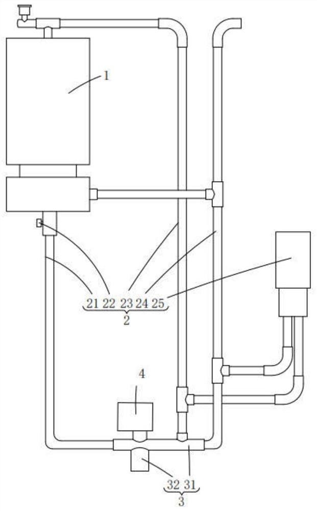
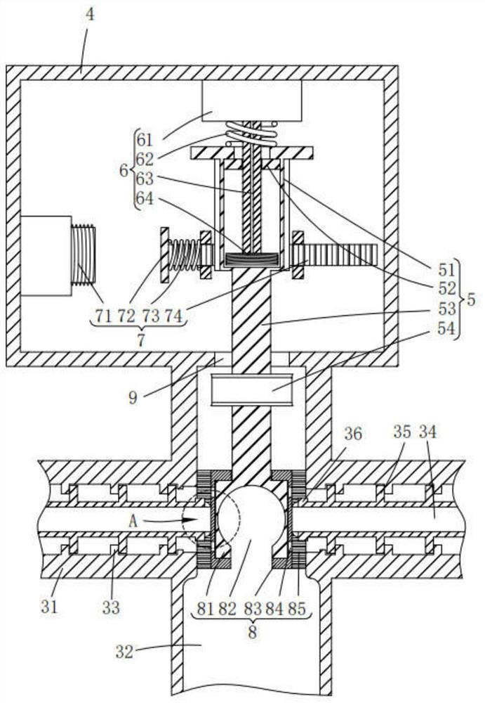
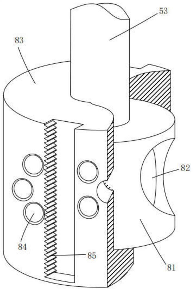
[0026] Please refer to figure 1 , figure 2 , image 3 , Figure 4 , Figure 5 , Figure 6 , Figure 7 , Figure 8 and Figure 9 ,in, figure 1 A structural schematic diagram of a preferred embodiment of the high-speed rail drainage structure provided by the present invention; figure 2 for figure 1 A schematic cross-sectional view of the transmission structure shown; image 3 is a structural schematic diagram of the valve body structure shown in Figure 2; Figure 4 for figure 2 A schematic cross-sectional view of the evacuated structure shown; Figure 5 for figure 2 The schematic diagram of the vertical section of the emptying structure shown; Figure 6 for figure 1 A schematic cross-sectional view of the first inner tube shown; Figure 7 for figure 2 The enlarged schematic diagram of the region A shown; Figure 8 for figure 1 Sc...


PUM


Abstract

The invention provides a drainage structure for high-speed rail. The drainage structure for high-speed rail comprises a water heater; a pipeline structure, which comprises a hot water drainage pipe, aswitch, a hot water pipe, a cold water inlet pipe, a faucet first inner pipe and a ball valve; an emptying structure, which comprises a collecting pipe, a drainage pipe, a first convex block, a second inner pipe, a second convex block and a gear; a housing; a transmission structure, which comprises a gear column, an iron block, a connecting column and a connecting pipe; a lifting structure, whichcomprises a fixed table, a first spring, a column body and a first electromagnet; a rotating structure, which comprises a second electromagnet, a magnet, a second spring and a rack; and a valve bodystructure, which comprises an inner column, a channel, an outer column, a communication port and a gear groove. The drainage structure for high-speed rail has the advantages of easy operation, thorough drainage, melting of iced water in the pipe and cleaning of incrustation.

Description

technical field [0001] The invention relates to the technical field of water for high-speed rail, in particular to a drainage structure for high-speed rail. Background technique [0002] The hot water supplied to passengers on the high-speed rail is generally heated by a water heater. The water heater can only release hot water when the external water source enters the heating device. In cold regions, especially in the north, the device for storing hot water in the water heater has The heat preservation effect can ensure that the hot water will not cool down for a long time, but the water in the pipeline needs to be drained in time to avoid the cold weather, the water in the pipeline will freeze and damage the pipeline; the general drainage device will have multiple The drain outlet controls the discharge of cold water and hot water separately. When discharging the remaining water, the operator needs to control multiple switches, which is time-consuming and labor-intensive. ...

Claims


Application Information

Patent Timeline
Patent Type & Authority Patents(China)
IPC IPC(8): B61D35/00
CPCB61D35/002
Inventor 方正夏军赵俊武王平
Owner 北京先河交通设备技术有限公司
Learn More