High-voltage power capacitor porcelain bottle transfer device

A transfer device and high-voltage power technology, applied in the field of electric power engineering, can solve the problems of poor use comfort, fixed storage capacity, inability to adjust, etc., and achieve the effect of convenient installation and disassembly, and strong practicability.

Inactive Publication Date: 2020-06-09
彭伟成
View PDF10 Cites 1 Cited by
  • Summary
  • Abstract
  • Description
  • Claims
  • Application Information

AI Technical Summary

Problems solved by technology

The card slots in the main frame and the clip strips on both sides of the box are convenient for the box to slide into the main frame. The operation is simple and convenient, and the box on the lower side is 10cm away from the partition, which prevents the top of the capacitor porcelain bottle from interfering with the partition. The friction and collision of the board, the hollow shape on the top of the main frame is also to prevent the capacitor porcelain bottle located in the upper box from colliding, but the storage capacity of the device is fixed and cannot be adjusted according to the needs of use, which cannot meet different use needs. poor comfort

Method used


Image

  • High-voltage power capacitor porcelain bottle transfer device
  • High-voltage power capacitor porcelain bottle transfer device
  • High-voltage power capacitor porcelain bottle transfer device

Examples


Embodiment 1

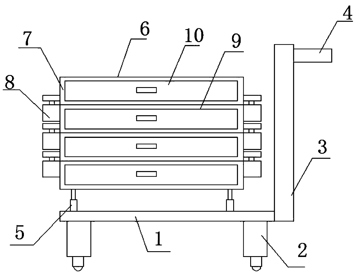
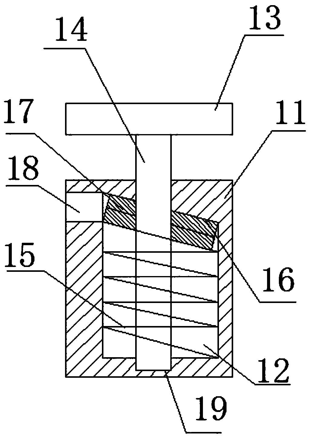
[0026] see Figure 1-4 , in an embodiment of the present invention, a high-voltage power capacitor porcelain bottle transfer device includes a base 1, a running mechanism 2 is provided on the underside of the base 1, a bracket 3 is provided on the upper right end of the base 1, and a bracket 3 is provided on the bracket 3. There is a push rod 4, and the upper side of the base 1 is provided with several first electric telescopic mechanisms 5, and the upper end of the first electric telescopic mechanism 5 is equipped with a transfer mechanism 6, and the transfer mechanism 6 is composed of several transfer seats 7, and the transfer seat 7 is provided with a cavity 9, and the cavity 9 is provided with a storage drawer 10, and the adjacent transfer seats 7 are connected by a connecting mechanism 8, and the connecting mechanism 8 includes a connecting seat 11 and a connecting plate 13. The connecting plate 13 and the connecting seat 11 are respectively installed on the two adjacent ...

Embodiment 2

[0029] On the basis of embodiment one, refer to Figure 4 , the walking mechanism 2 includes a leg 26, the inside of the leg 26 is provided with a housing cavity 27, and the inside of the housing cavity 27 is provided with a shock-absorbing support mechanism, and the shock-absorbing support mechanism includes a The shock absorbing mechanism 28 on the cavity 27, the lower end of the shock absorbing mechanism 28 is provided with a shock absorbing plate 29 that is slidably connected with the accommodation cavity 27, and the lower side of the shock absorbing plate 29 is provided with a supporting walking mechanism. The running mechanism includes a second electric telescopic mechanism 30 installed on the shock absorbing plate 29, the lower end of the second electric telescopic mechanism 30 is equipped with a support seat 31 which is slidingly connected with the accommodating cavity 27, and the lower side of the support seat 31 A universal wheel 32 is provided, and a locking mechani...


PUM


Abstract

The invention relates to the field of electric power engineering, and concretely relates to a high-voltage power capacitor porcelain bottle transfer device. The device comprises a base, a transferringmechanism is composed of a plurality of transfer seats, a cavity is formed in each transfer seat, a storage drawer is arranged on each cavity, the adjacent transfer seats are connected through a connecting mechanism, each connecting mechanism comprises a connecting seat and a connecting plate, the connecting plate and the connecting seat are respectively mounted on two adjacent transfer seats, aconnecting rod is arranged at the lower side of each connecting plate, a limiting cavity is formed in each connecting seat, an inclined face is arranged at the upper end of each limiting cavity, a plurality of limiting rings are arranged at the positions, close to the inclined face, in each limiting cavity, springs are arranged on the lower sides of the limiting rings, the lower ends of the springs are connected with the lower ends of the limiting cavities, and the connecting rods are inserted into the limiting cavities and penetrate through the limiting rings. Due to the structural arrangement of the device, the number of the transfer seats can be increased or decreased according to the number of products needing to be transferred, different use requirements are met, and practicability ishigh.

Description

technical field [0001] The invention relates to the field of electric power engineering, in particular to a high-voltage power capacitor porcelain bottle transfer device. Background technique [0002] The main raw material of high-voltage power capacitor porcelain bottles is ceramics, which are fragile when collided. As the main electrical insulator of high-voltage power capacitor units, porcelain bottles are widely used in high-voltage power capacitors. The specifications are now mainly six umbrellas, ten umbrellas and thirteen umbrellas. [0003] When the capacitor unit is manufactured, the sleeve of the porcelain bottle is first welded with the stainless steel upper cover. After the welding is completed, it needs to be transferred and assembled with the capacitor core. damage. [0004] Chinese patent (Notice No. CN 209833727 U) discloses a high-voltage power capacitor porcelain bottle transfer device, with a shock absorbing plate at the bottom of the main frame, shock ab...

Claims


Application Information

Patent Timeline
Patent Type & Authority Applications(China)
IPC IPC(8): B62B3/04B62B5/00
CPCB62B3/04B62B5/00B62B5/0006B62B2202/02
Inventor 彭伟成
Owner 彭伟成
Why Eureka
Try Eureka